ARCBRO Voyager 1220 User Manual Download Page 26

Service Support Spirit         


26 

Unique Solution         

                           WWW.ARCBRO.COM


8. Automatic Function(AUTO) 

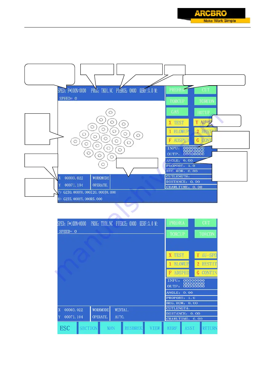
In the main menu, press [F1] to enter the automatic function window, as shown in the figure below.   


Flame mode 


Fig. 8.1 Automatic Function (AUTO) Window 

Plasma Mode 

Active speed 

multiplying factor 

Program 


Heavy-current control 


Piercing Hole 


Kerf 

Input/output 

indication 

Function 


Coordinate


Pattern 

Display 

Space 

Machining 

parameter 

indication 

Work mode 


Machining   

Program 

Summary of Contents for Voyager 1220

Page 1: ...Cutting Machine User s Manual Reference P 218 3 Issue 1 Revision 1 Date of issue January 2017 ARCBRO Xinfang Industrial Park NO 218 ChaoYang District 100024 Beijing China Tel 86 10 65798995 Fax 86 10...

Page 2: ...o parts of this manual may be reproduced stored in a retrieval system or transmitted in any form or by any means electronically mechanically by photocopy recording or otherwise without the prior writt...

Page 3: ...ion instruction for Auto Flame cut 19 5 Installation of Nesting Software 21 6 Functional Overview 22 6 1 System Functions 22 6 2Technical specifications 23 7 Main Menu 24 7 1 Menu Features 24 7 2 Desc...

Page 4: ...urn at G00 when reach a piercing point 34 8 5 4 Repeat the above operation procedure until the desired effect is achieved 35 8 5 5 To exit machining mode 35 8 5 6 Total row number and beginning row in...

Page 5: ...on 54 12 2 SETUP parameter setting 55 12 2 1 Speed parameters 55 12 2 2 System parameters 56 12 3 Flame Cutting Parameters 58 12 4 Plasma Parameters Setting 59 12 5 Control Parameters Setting 60 13 LI...

Page 6: ...ry 24 kinds of shapes External format TXT or NC format Language English Chinese Spanish Russian French Japanese Czech and Slovenia PLASMA CUTTING MODE Max cutting speed 6000mm min Max cutting thicknes...

Page 7: ...oftware standard Wizard is included in standard package Note 4 The machine must be grounded reliably when it is working Connect the plate and the earth Note 5 Clean dust regularly to keep the rail and...

Page 8: ...sed in industry field widely It can cut and blanking metal plates such as carbon steel flame cutting stainless steel copper and aluminum plasma cutting 1 3 Starting Programming and Nesting The Compute...

Page 9: ...elected according to the cutting to be performed 8 Only Oxygen gas is available as combustion supporting gas 9 The Acetylene or Propane or Methane or Gasoline can be used as fuel gas 10 Adjust the gas...

Page 10: ...handle with care Put down prevent hands and feet were clipped by machine Be careful equipment dumping or tip over 18 The machine should be each half a month for rack and pinion with lubricating oil 1...

Page 11: ...t in the boxes are protected fully to avoid any damages during transportation The boxes have to be carried with care always and with the top cover up during handling and transportation 3 2 Packing Lis...

Page 12: ...ture 2 Take 16 pieces M5 bolts and square pad out put 8 pieces nuts into the channel on each inner side of the aluminium frame with 4 pieces in each end of the two sections Show as picture1 Picture1 O...

Page 13: ...ail tightly fitted 4 Take out the 16 bolts plug in 8 pieces for each side and tighten them with the corresponding nut show as picture 3 Picture3 tighten all the screws one by one Picture 4 the connect...

Page 14: ...olts on it out plug the 4 quadrate nuts of cushion block into the channel from the end of the rail show as picture 6 Repeat the last step assemble the other longitudinal cushion block and have the cen...

Page 15: ...e Transversal cushion block and have them fixed to the point that 1000mm to each end of the frame Picture 7 Fix the 2 blocks 1000mm to the end of the frame 8 Take another two pieces of the 1000mm with...

Page 16: ...l is finished 4 3 Installation of the CNC controller 1 Turn around the rail to back side install rail connect plate by 16 bolts as Picture 2 shows 2 Align the wheels of the Controller unit and the gui...

Page 17: ...OM 9 4 Ground wire connection Find the Ground wire point on the longitudinal rail frame 100mm from the end Plug the nut into the channel and screw it up Clamp its other end to the plate you want to cu...

Page 18: ...closure used for torch ignition 3 ARC START 4 DIV ARC Input CNC IN2 Receive the signal of raw arc voltage from plasma normally the value of the voltage is between 50VDC to 300VDC J27 DIV ARC J28 9 5...

Page 19: ...9 6 Connection instruction for Auto Flame cut Assemble part Presentation Qty Part No CHC holder device for flame auto height control Optional 1 unit ARC153049 80mm neck flame torch and hose 1 unit ARC...

Page 20: ...ts screw 2 Clamp the CHC holder device onto the flame torch above the standard torch holder 3 Fix the screw of the CHC holder well 4 Connect the two ends of white Solenoid Valve cable plug Note If the...

Page 21: ...ins one CD and one dongle The software installation file and function instruction videos are written in the CD for your reference Match with the PC system WINDOWS XP WIN7 WIN8 WIN8 1 and WIN10 and Par...

Page 22: ...covery and automatic breakpoint memory Random section and piercing point selection Extended piercing for thick plate and bridging feature for thin plate Optional piercing position feature in mode of R...

Page 23: ...tical isolation output Interlocked axles 2 axles extensible to 4 interlocked axles Maximum speed 24m min Pulse equivalency variable electronic gear numerator and optional denominator in the range from...

Page 24: ...rntothe upperlevelofmenu 7 2 Description of Main Menu VER Theversioninformationofsoftwareandhardwareisindicatedatthebottomleftcorner foryourinformation F1 AUTO Programmedcontrolofautomaticmachining F2...

Page 25: ...lution WWW ARCBRO COM G G 3 InitialSetting Adialogboxasfollowswillappear Fig 7 2 Initial setting dialog box Fileformat toformat user s program space Parameter To restorethe factoryparametersetting ENG...

Page 26: ...heautomaticfunctionwindow asshowninthefigurebelow Flamemode Fig 8 1AutomaticFunction AUTO Window PlasmaMode Active speed multiplying factor Program Heavy current control Piercing Hole Kerf Input outpu...

Page 27: ...the Metric English SelectioninSETUP RefertoParameterControl 8 1 2 PROG PIERCE and KERF Theyareusedtoindicatethenameofmachiningprogram serialnumberofpiercedhole automaticclearin automaticmachiningmode...

Page 28: ...machining case rise the cutting torch M72 open the cutting oxygen M12 and lower the cutting torch M73 Plasma machining case execute 07 command Note This is a very important feature It will be used rep...

Page 29: ...sed when machining needs to start from a certain section or only a part needs being processed Refer to SECTION feature for details 8 2 2 F2 MAN To switch the system to manual mode 8 2 3 F3 RESBREK Aft...

Page 30: ...ection is taken as positive angle 8 2 7 2Example The system is able to identify and calculate the rotation angle by measuring the origin point and the end point of an edge of steel plate a straight li...

Page 31: ...ize will magnify or minify as per this scale This feature is very useful in cutting graphic character 8 2 10 F2 WENTAI The system will prompt to run WENTAI based machining program if this key is press...

Page 32: ...omatic mode 1 PAUSE If this key is pressed the system will slow down and stop movement shut off cutting oxygen shut off arcing switch in plasma machining case turn off the height controller M39 and re...

Page 33: ...many workpiece or large size of workpiece it might be necessary to relocate the cutting torch 8 4 2 2Situations allowed to adjust the cutting position 1 pause process 2 return process 3 piercing proc...

Page 34: ...andthenpress START keytoselect appropriateoperation 8 5 Original Path Return When it is necessary to return the cutting torch along the original path due to failure to cut through in machining operati...

Page 35: ...lifts or continue machining if the cutting torch lowers or For plasma cutting operation ignite arc and do not go on machining until the arc ignition is completed 8 5 4 Repeat the above operation proc...

Page 36: ...tting torch Refer to 3 4 for details 4 If the position of cutting torch changed not at the breakpoint any more the system will provide three options when a program breakpoint is found which is virtual...

Page 37: ...or keyandmakeonechoicefromtwomachiningoptions Accordingtoyouroption thesystemwillprompttoinputtheserialnumberoftheoption program linenumberortheserialnumberofpiercingpoint 8 7 2 Two cases for SECTION...

Page 38: ...he piercing point and then perform the operations as above 8 8 MOVE HOLE for Thick Plate 1 In automatic mode MOVE HOLE option is taken for thick plate 2 For edge piercing method it is important to mov...

Page 39: ...ime thespeedmultiplyingfactorisadjustedto5 automatically Thesystemis preheated 2 Press START key at the end of preheat The cutting torch will reach the piercing point along a straight line at selected...

Page 40: ...ual mode window plasma cutting operation Manual mode window flame cutting operation Fig 9 1 Manual mode window Active speed multiplying factor Program Heavy current control output Piercing Kerf Input...

Page 41: ...cutting torch will stop if the corresponding direction key is pressed while the other axial movement will go on until the corresponding direction key is pressed too PAUSE key will stop the movement as...

Page 42: ...7 Speed Atthetopleftcornerofthescreen itshowsF speedmultiplyingfactorinmanualmode manualspeed Itisallowedtoadjustthespeedquicklybypressing F keyinthiswindow Apull downmenuwillappearwith8 speedmultipl...

Page 43: ...it is used to load a program into the user program area The system will tabularize the available program names and highlight the current program name Move the cursor key to select different programs...

Page 44: ...USB disk instead of saving it 10 1 4 F4 DELE It is used to delete the program in the user program area 10 1 5 F5 DELL To delete a full program line in editing area and improve editing efficiency 10 1...

Page 45: ...ce between the coordinate value of circle center and X axis original value in arc cutting operation J The difference between the coordinate value of circle center and Y axis original value in arc cutt...

Page 46: ...G91 Absolute Relative Coordinate Commands When using G90 X Y represent coordinate values and U V represent the values relative to the current point when using G91 X Y and U V all represent the values...

Page 47: ...torch will move along a straight line from the origin point to the end point at the speed of the maximum speed limit multiplied by multiplying factor G00 movement is subject to speed multiplying facto...

Page 48: ...e center relative to the origin point in X axis and Y axis respectively distance between the circle center and the origin point R is the radius of circle R is a positive value and can be used to repre...

Page 49: ...the cutting torch return to the reference point automatically Format G26 Return to the reference point along X axis G27 Return to the reference point along Y axis G28 Return to the reference point si...

Page 50: ...41 is to compensate a half diameter of flame leftwards along the machining path G42 is to compensate a half diameter of flame rightwards along the machining path G40 represents end of offset Since cut...

Page 51: ...is as follows 1 Open acetylene gas valve and ignite the torch if the valve is not open 2 Lower the cutting torch for time delay of torch lowering see M71 command 3 Open the oxygen preheating valve an...

Page 52: ...valve M12 or turn on plasma arc ignition and check for the signal of Arc Voltage Successful 3 Lower the cutting torch M73 There is no this step in plasma cutting operation 4 Switch on height controll...

Page 53: ...g oxygen valve is opened this command is used to move the torch to the cutting position opposite to M72 in function and little bit smaller in value Because of gravity the lowering action is faster tha...

Page 54: ...verse backlash line bias and soft positive negative limit switch in every axis Flame cutting parameters Ignition delay preheating delay torch lifting lowering delay lifting lowering of piercing torch...

Page 55: ...meters it is suggested to set the factory parameters as active parameters otherwise the modifications will be validated to the active user parameters 12 2 SETUP parameter setting 12 2 1 Speed paramete...

Page 56: ...takenaswell smallervalueforworsevibration Circularcornertransitionaloption Ifthisoptionisenabled value 1 thesystemwillnotdecelerate throughacirculartransitionwhentherunningdirectionchangeofsystembetwe...

Page 57: ...areferencedistance thelonger themoreaccurate Measuretheactual traveldistanceandtakethemeasuredvalueintothefollowingformula NumeratorXActualTravelDistance Simplifytheaboveformulatoafractioninlowestterm...

Page 58: ...etimedelaywhenturnonthehighvoltageignitionswitchifM20isexecutedinflame cuttingoperation Preheatingdelay Itisthepreheatingtimeforpiercingoperationinsecond Ifthepreheatingtimeis insufficient itwillbepro...

Page 59: ...numberbutunequaltoeachother itimpliestherearetwooutputportsseparatelycontrolthe openingandclosingoperations Inthiscase thesystemusespulsecontrolwithpulsewidthof0 5second Arcvoltagetestoption Itisusedt...

Page 60: ...htcontrolin suchadistancefromtheendpoint inmm 12 5 Control Parameters Setting IntheSETUPsubmenu press F5 keytoentercontrolparameterssettingwindow asshowninFig 12 6 Flame plasmaoption Take0forflamemach...

Page 61: ...tofsteelplatealongYaxis whichisenabledonlyinrunning extralargeprogram Commonedgeoption Sincethesystemmaycontrolthreekinematicaxes thisoptionisusedto determinethe3rdaxis Zaxis sharesacommonedgewithXaxi...

Page 62: ...lchecktothephysicaldimensionsandprompt warningmessageifanyerrorisdetected Notes 1 It is impossible for the control system to find all the error parameters therefore please enter correct dimensionsforp...

Page 63: ...l prompt at the upper right corner to input parameters for the pattern as show in Fig 13 2 F1 Workpiece To machine into workpiece that is solid internally F2 Hole To machine into hole that is solid ex...

Page 64: ...17S NC which should have the following structure G92 X0 Y0 User defined module Note The original program should not have more than 59 lines G28 The last line should command the torch to return to the...

Page 65: ...ter DIAGNIZE main window as shown in the figure below In Plasma Operation In Flame Operation 14 1 Check Input output Ports The system diagnosis will show the hardware resources available In DIAGNOSE w...

Page 66: ...and 1 1 stands for enable while 0 stands for disable Refer to Definitions of Input output Port for the definitions of output ports 14 3 Input Check Let the system to show the state of active optical i...

Page 67: ...ram upgrading is successful the system will prompt Upgraded Successfully and sound one beep If program upgrading fails the system will prompt Upgrade Failure and sound continuous beeps 4 New program s...

Page 68: ...y more an d gives no response t o any keystroke espe cially to the pause ke y The machine operation is interrupted a Remove the interference and make sure the grounding wire o f plasma power supply is...

Page 69: ...ection or dis connection exists Secure the connection If no external limit sw itch is connected chec k the system if the cu rrent coordinate values are too high and out of the travel limit se t by sof...

Page 70: ...for LCD for any loos e connection Secure the connection USB transmis sion failure USB disk is not comp atible with the syste m Try the USB disk of other mode l or brand Incorrect format of U SB disk...

Page 71: ...input end must be connected to 24V ground wire d A 0 01uF capacitor should be used between the 24V ground wire and encl osure shielded cable e Use an isolation transformer 380V 220V and as interferenc...

Reviews: