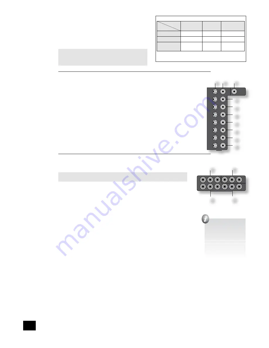
background image

AVR280

8

Video connections

The AVR280 allows for conversion between different video 
formats. This means that the AVR280 can convert between 
composite, S-video and component, if required. For example, if 
you are watching a composite input from a VCR, you may view 
it from the S-video or Component/RGB video outputs of the 
AVR280. This allows you to use a single (typically high-quality 
Component/RGB) connection between the AVR280 and your 
display device.

The record loops do 

not

 work from the video converter. 

This means that to record a S-video or composite signal, 
a S-video or composite signal (respectively) must be 
supplied.

Composite/S-video video connections

dm


dn


MONITOR OUT

.  

Two video output connectors are provided, one for S-Video and one for composite video. The outputs 
carry the same information at all times (and both may be used simultaneously, if required). 
Connect one of these outputs to the video input of your display device.

dq


VCR IN

ds


AUX IN

dt


AV

ek


SAT

el


DVD

.  

Connect the composite video outputs of your source equipment to these inputs. The choice of 
connection to use (S-video or composite) depends on where the signal is to be routed to: if the 
signal is to be used in Zone 2, then a composite connection is required; if the signal is to be used 
for recording (routed to a VCR, for example), then the connection type must match the connection  
to the recording device (i.e., if the recording device requires a S-video signal, then a S-video 
connection from the source equipment must be used). 
If both connections are made, the signal from the S-video input will be used for the main zone if no 
Component/RGB signal is supplied.

dp


VCR OUT, 

dr


AUX OUT

.  

Connect one of the S-video or composite video outputs to the video input of your VCR or AUX. The 
connection used must match the video type of the source you wish to record (as described above). 
For example: if you wish to record a S-video signal from your satellite receiver on your VCR, the 
connection to the VCR must also use S-video.

High quality (Component) video connections

These inputs are suitable for connection to component (YUV/YCrCb) or RGB outputs. These 
signals are usually available from a DVD player, set-top box or games console and offer the 
best possible picture quality.

Note that the high-quality component video connections operate independently of the 
composite/S-video connections.

Generally, the component video standard is used in North America/NTSC regions, while RGB 
is used in Europe.

em


AV

eo


DVD

ep


SAT INPUTS

. Connect the video outputs of your high-quality video sources 

to these inputs.

en


HIGH QUALITY VIDEO OUT

. Connect these sockets to the component video inputs of your 

display device.

Important notes about HQ-video inputs and outputs

In the ‘Video Settings’ set-up menu, each of these three high-quality component video 
inputs can be allocated individually to any of the other inputs, e.g., the input labelled 
‘DVD’ does not have to be used for DVD, but can be used for something else. See page 
14 for further details.

You cannot mix component and RGB sources. Selection of component or RGB can be 
made in the Set-up menu ‘General Settings’ page (see page 10).

The high-quality component video inputs have sufficient bandwidth for line-doubled 

NTSC (525/60) or PAL (625/50) video (‘progressive scan’) and also US HDTV video 
signals. However, when used with such signals the OSD is not overlaid on the picture 
but is output at standard interlaced NTSC or PAL (525 or 625 line) rate on a solid 
background.

When using the HQ-video inputs, the composite and S-video outputs will be muted. This 
is because the processing for the on-screen display would create invalid video signals on 
these outputs.

SCarT rGB 4-wIre ConneCTIon

(SCART refers to the multipole A/V connector used commonly on European A/V equipment.)
Some video projectors and most European TV sets require the use of a 4-wire RGB connection, where 
the ‘sync’ signal is separate from RGB. In this case, you need to use the composite video 

MONITOR 

OUT


dn

 for the sync information. A cable is available from your dealer to make this 4-wire RGB 

connection (refer to the table of SCART connections at the back of the manual). Note that use of this 
feature requires (in addition to the RGB connections) a composite video connection between the source 
and the AVR280, in order to supply the additional synchronisation signal.
Note that most SCART TV inputs will require the SCART RGB status line to be controlled before the RGB 
signal will be displayed. The RGB trigger output will control this signal when connected to the SCART 
socket using a cable of the type given on page 32. These cables are available from your dealer.
The AVR280 does not support either 5-wire RGB HV or 3-wire RGB sync-on-green connections.

�����

���

��

���

���

��

���

��

���

���

���

���

�����

�����

���

��
��
��
��
��
��

��

�� �� ��

��

���

���

���

���������������������

��

��

��

��

The following video conversions are possible:

             To:
From:

Composite

S-video

Component/
RGB

Composite

Yes

Yes

Yes

S-video

Yes

Yes

Yes

Component/
RGB

No

No

Yes

Note that conversion between RGB and Component video 
(or vice-versa) is not supported by the AVR280.


when you connect 

your devices to these 
connectors, take care to 
follow the letter/colour 
coding for each input. 
no damage will occur if 
connected incorrectly, 
but unusually coloured 
or unstable pictures will 
result.

Summary of Contents for AVR280

Page 1: ...AVR280 HANDBOOK Arcam AVR280 surround sound receiver English ...

Page 2: ...tand that is recommended for use with audio equipment If the equipment is on a portable rack it should be moved with great care to avoid overturning the combination 8 Cleaning Unplug the unit from the mains supply before cleaning The case should normally only require a wipe with a soft damp lint free cloth Do not use paint thinners or other chemical solvents for cleaning We do not advise the use o...

Page 3: ...tion 27 Digital multi channel sources 27 Two channel source modes 28 Multi channel source modes 28 DSP Effects Modes 29 Speaker positioning 29 Bi wiring and bi amping loudspeakers 30 Before you start important information 30 Bi wiring your loudspeakers 30 Bi amping your system 30 Troubleshooting 31 SCART connections 33 IR Remote Codes 34 Technical specifications 36 Guarantee 37 Worldwide Guarantee...

Page 4: ...n a listening room is an important process which requires care at every stage For this reason the installation information is very comprehensive and should be followed carefully Using this handbook Thank you for purchasing the Arcam AVR280 Surround Sound Receiver This handbook has been designed to give you all the information you need to install connect set up and use the Arcam AVR280 Surround Sou...

Page 5: ...nversion for Zone 2 For these reasons we recommend that source devices that have a digital connection are also connected to the analogue inputs High quality YUV RGB and S video sources should also have their composite outputs connected to the AVR280 for use in Zone 2 Using the remote control The remote control requires four AAA batteries to operate To insert the batteries into the remote control p...

Page 6: ...DVD or VCR but all inputs have the same circuitry This means that there is no reason why you should not connect a different device from that labelled to any of the inputs For example if you had two DVD players and the AV input was not being used then the second DVD player could be connected to the AV input Cables We recommend the use of high quality screened analogue digital and video cables since...

Page 7: ... there is no bass management for DVD A or SACD players In this case the bass management functionality of the player itself should be used Stereo outputs 1 VCR OUT 3 AUX OUT bq TAPE OUT Connect the left and right audio outputs sockets to the left and right input sockets of your cassette deck VCR or AUX usually labelled RECORD IN The VCR AUX connections may also be used for a second or third cassett...

Page 8: ...ect the video outputs of your high quality video sources to these inputs en HIGH QUALITY VIDEO OUT Connect these sockets to the component video inputs of your display device Important notes about HQ video inputs and outputs In the Video Settings set up menu each of these three high quality component video inputs can be allocated individually to any of the other inputs e g the input labelled DVD do...

Page 9: ...ring to the labels on the rear panel When connecting the speaker terminals of the amplifier with the terminals on the speakers make sure that like polarities are matched i e match with usually red and with usually black Mismatching of polarities will result in a weak central sound unclear orientation of the instruments and the sense of direction of the stereo being impaired There are two options f...

Page 10: ...ses you should have sockets in your home marked FM or VHF do not use those marked TV which should be connected to the FM in socket fr of the AVR280 If you wish to use the supplied FM ribbon cable mount this as high up as possible on a wall with the T elements positioned horizontally Try each usable wall of the room to see which gives best reception and use tacks or adhesive tape to secure the aeri...

Page 11: ...red as shown in the panel fm VIDEO TRIGGER 1 fl VIDEO TRIGGER 2 These trigger outputs have different functions depending on how the Video Status has been set in the General Settings menu See page 10 for full details Connecting to a power supply fo Power inlet The AVR280 has a dual voltage power supply that can be switched between 120V and 230V AC As supplied this switch should be set correctly for...

Page 12: ...ars Pressing the menu button for just a short time will take you to Main Menu Screen 1 If this happens the Main Menu can be closed by pressing menu for a second time 2 When the menu heading is highlighted using the D and E keys will navigate between menu pages Using this method to navigate between pages the first time the unit is being configured will help to ensure that no pages are missed out 3 ...

Page 13: ...e the video triggers or a SCART connection then it does not matter which value this item has This item has four settings Composite S video RGB and Scrn Ctrl Composite This mode is used to indicate to your TV that composite video is being sent It uses the trigger labelled 1 RGB fl which should be connected to the RGB SCART input on your TV as shown Select this option if you are using the composite ...

Page 14: ...frequency at which bass redirection begins Frequencies below this level are redirected from small speakers to the Fronts or to the subwoofer frequencies above this level are not redirected The value for this setting depends on your speakers environment and taste and is best determined by experimentation The adjustment can be made in increments of 10Hz between 40Hz and 130Hz Stereo Mode Select betw...

Page 15: ...ti channel analogue outputs of an Arcam DVD A player then this item should be set to 10dB 4 Speaker Delay Settings The relative positioning of speakers within a room may mean that sound from some speakers arrives at the listener later than sound from others By altering the delay settings for the different speakers this difference in arrival time can be reduced or eliminated When setting the delay ...

Page 16: ...peaker that is not selected in the previous Speaker Sizes menu Note that inserting headphones into the front panel of the AVR280 will cause all test tones to be muted including the headphone output NOTE If you are using a 6 1 speaker configuration a single surround back speaker we recommend connecting the surround back speaker to the surround back left channel of the AVR280 In this case the level ...

Page 17: ... Inputs Composite and S video inputs for DVD Sat AV VCR and AUX have their audio and video assigned to track each other by default The five Video Input lines for Tape CD FM AM and DVD A allow assignment of a video source to these normally audio only sources If desired it is possible to allocate the same video source to more than one audio input This facility allows you to listen to an audio source...

Page 18: ...ogue inputs in Volts rms so that each one achieves the optimum dynamic range and sounds similar in loudness to the others Available level settings are Low 0 5V Medium 1V Reference 2V High 4V The reference level of 2V should be appropriate for most inputs If a source is very quiet compared with the other sources you can increase its loudness by selecting the Medium 1V or Low 0 5V settings ADV 6 HDM...

Page 19: ...hift C to Power off Shift E to switch Zone 2 on Shift D to switch Zone 2 off Source selection only 1 DVD input 2 CD player input 3 Television sound input 4 Auxiliary line input 5 Video Cassette Recorder input 6 Satellite decoder input 7 DAB FM AM tuner input Press the relevant button once to select input MUTE Press once to mute the main system Press again or use VOL to un mute VOLUME Adjusts the s...

Page 20: ...gh effects modes for two channel sources FM MONO Toggle Mono output on FM FAV Restores current favourite preset DIRECT Toggles CD Direct mode SYNC Displays the Lip sync adjustment menu Press again to exit EQ Toggles the room equalisation function on off if available THX In Zone2 use this button to enable Follow Zone1 mode AVR280 does not support THX P TUNE Toggle Preset Tune radio mode ...

Page 21: ...button on the remote control Volume control To adjust the volume level of the loudspeakers pre amp outputs and headphones use the volume control knob The volume level is shown on the display Note that different sources may require different settings of the volume control to achieve the same perceived volume level It is important to realise that the value indicated for the volume level is not an ac...

Page 22: ...ent source from CD will cause the recording to change to this new source VCR AUX Operation The AVR280 has VCR and AUX record loops for audio and video Composite and S video only These carry the audio and video if any from the currently selected source The VCR output is muted if VCR is the selected source the AUX output is muted if AUX is the selected source Example If you want to record the SAT in...

Page 23: ...tings in Speaker Eq is still 6dB not 12dB To select the speaker to be adjusted press the Treble Bass button repeatedly until the desired speaker is shown on the front panel display Then use the volume control knob to adjust the setting up or down Note that bass and treble alterations are not available in Stereo mode when Auto Stereo Tone BypasS is set to Yes or in Stereo Direct mode Remote control...

Page 24: ...you wish to store Press the STORE button or DYN on the remote control the station frequency is shown on the display followed by a preset number Select the preset number you wish to assign to the station using the 3 and 4 buttons on the front panel or P or P on the remote control handset then press the STORE button again Once the preset is stored the display reverts to show the station name if RDS ...

Page 25: ...select buttons on the front panel or the remote Note that changing the audio input also changes the video input to the same setting Video Input This shows the current video input source selected The current video input can be changed when this line is highlighted using the source select buttons on the front panel or the remote Changing the video input does not change the audio input so you can wat...

Page 26: ...immersive result We recommend Dimension is set to 3 for normal use Centre Width With Pro Logic decoding dominant centre signals come only from the centre speaker If no centre speaker is present the decoder splits the centre signal equally to the left and right speakers to create a phantom centre image The Centre Width control allows variable adjustment of the centre image so it may be heard only f...

Page 27: ... remember this for all bitstream sources e g DTS ES Matrix Dolby Digital 3 0 etc and use the maximum number of speakers the signal is encoded for As a result when a 2 0 or 2 1 bitstream is played the Surround mix mode is recalled and the AVR280 enters Dolby Pro Logic IIx Movie mode to try to recreate the surround environment from what may be a Pro Logic encoded source If you would rather listen to...

Page 28: ... stereo sources can sound muffled and compressed DTS NEO 6 DTS Neo 6 provides up to six full band channels of decoding from stereo material The AVR280 will derive separate channels corresponding to the standard home theatre speaker layout Cinema A movie mode designed to reproduce a movie theatre environment Neo 6 technology allows various sound elements within a channel or channels to be steered s...

Page 29: ... surround left surround right left surround back right surround back and an active subwoofer see diagram All speakers with the exception of the subwoofer should be arranged around your normal viewing listening position see diagram The subwoofer should be placed in accordance with the instructions of the manufacturer experiment with it in various positions to obtain the best result Front left and r...

Page 30: ...peaker terminals the speakers will still be single wired 2 Connect the cables as shown in the diagram ensuring correct polarity at all times Bi amping your system Notes In order to bi amplify your speakers your speakers will need to be bi wirable have positive and negative terminals for both high frequency HF and low frequency LF information If your speakers are bi wirable ensure that the links be...

Page 31: ...en the HQ Video setting is set to RGB you will have a pink red OSD To correct this you must set the HQ Video line on the General Settings menu to Component No On Screen Display OSD overlaid on video The AVR280 cannot overlay video onto progressive scan or HDTV signals In this case the AVR280 creates a full screen display with a black background for the menus and turns off the pop up messages No so...

Page 32: ...2 Settings in the Set up Menu When Zone 2 is put into stand by the main zone is also turned off Check that the Zone 2 Stand by line of Zone 2 Settings in the Set up Menu is set to Local Only Unstable OSD on screen display The AVR280 defaults to the NTSC video standard for US units and PAL for European units If your display device is unable to display the default video standard attach a source comp...

Page 33: ... and 7 Sleeve Coaxial cable 6 and 7 18 Ground RGB switching control Stereo Mini Jack 3 5mm Sleeve Screened cable 19 Video output composite RCA Phono 6 Centre Coaxial cable 6 Comp out 20 Video input composite RCA Phono 7 Centre Coaxial cable 7 RGB sync Comp in 21 Common ground shield SCART Sleeve Overall Cable Screen SCART S video cable with audio back to processor Pin Signal Connector Type Connect...

Page 34: ... Command code Command Command code Stand by 124 Mode 32 On 123 Mono mode 106 Zone 1 stand by 125 Stereo mode 107 Power toggle 12 Dolby PLII Movie 108 Display DIS 59 Dolby PLII Music 109 Menu Menu 82 Reserved 102 Info 55 Dolby PL Emulation 110 DTS Neo 6 Cinema 111 Mute 119 DTS Neo 6 Music 112 Un mute 120 Dolby PLIIx Movie 103 Mute toggle MUTE 13 Dolby PLIIx Music 104 Volume up 16 Reserved 105 Volum...

Page 35: ...if pressed for 1 second 5 Command Command code Preset 6 preset 14 if pressed for 1 second 6 Preset 7 preset 15 if pressed for 1 second 7 Preset 8 preset 16 if pressed for 1 second 8 Preset 9 9 Preset 10 110 Preset 11 111 Preset 12 112 Preset 13 113 Preset 14 114 Preset 15 115 Preset 16 116 Preset 17 117 Preset 18 88 Preset 19 89 Preset 20 90 Preset 21 91 Preset 22 92 Preset 23 93 Preset 24 94 Pres...

Page 36: ...6kHz Digital output level impedance 0 5V 75Ω Trigger outputs Output D C voltage level excl RGB status 12V 1V Allowable load 30mA max min 400Ω Remote inputs and output Signal modulated 36kHz carrier Coding Philips RC 5 General Mains voltage 110 115V and 230 240V switchable Power consumption maximum 1000VA Dimensions W x D x H including feet 433 x 420 x 145mm Weight net 15 9kg Weight packed 21 0kg S...

Page 37: ...ansportation costs at any time Claims under guarantee This equipment should be packed in the original packing and returned to the dealer from whom it was purchased or failing this directly to the Arcam distributor in the country of residence It should be sent carriage prepaid by a reputable carrier NOT by post No responsibility can be accepted for the unit whilst in transit to the dealer or distri...

Page 38: ...A R Cambridge Ltd Pembroke Avenue Waterbeach CAMBRIDGE CB25 9QR England www arcam co uk Issue 2 SH182 ...

Reviews: