background image

- 63 -

BOS

Pressing <Enter> on this item and it asks for confirmation:

Save configuration changes and exit setup?

Pressing <OK> stores the selection made in the menus in CMOS - a special 

section of memory that stays on after you turn your system off. The next 

time you boot your computer, the BIOS configures your system according to 

the Setup selections stored in CMOS. After saving the values the system is 
restarted again.

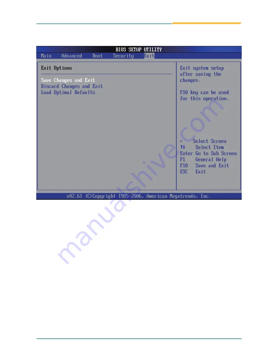
3.4  Exit Options

Save Changes and Exit

Discard Changes and Exit

Exit system setup without saving any changes. 

<ESC> key can be used for this operation.

Summary of Contents for Gladius G0710

Page 1: ...Gladius G0710 S Rugged Tablet PC User s Manual Version 1 0 2009 12 P N 4012071000100P...

Page 2: ...This page is intentionally left blank...

Page 3: ...1 Packing List 2 1 2 Ordering Information 2 1 3 Specifications 3 1 4 Dimensions 5 1 5 Introduction 6 1 5 1 Front Side 7 1 5 2 Function Buttons 8 1 5 3 LED Indicators 8 1 5 4 Rear Side 9 1 5 5 Right Si...

Page 4: ...t Control Panel 43 2 7 Function Key Tray 50 2 7 1 Function Key Configuration 50 Chapter 3 BIOS 51 3 1 BIOS Main Setup 52 3 2 Advanced Settings 53 3 2 1 IDE Configuration 54 3 2 2 Brightness Default Le...

Page 5: ...d the CE test for environmental specifications Test conditions for passing included the equipment being operated within an industrial enclosure In order to protect the product from being damaged by ES...

Page 6: ...2 Place this equipment on a reliable surface when installing Dropping it or letting it fall may cause damage 3 Make sure the correct voltage is connected to the equipment 4 For pluggable equipment the...

Page 7: ...s obvious signs of breakage 13 The sound pressure level at the operator s position according to IEC 704 1 1982 is no more than 70dB A 14 Keep this User s Manual for later reference 15 DO NOT LEAVE THI...

Page 8: ...local authority or ask the shop where you purchased the product or if applicable follow any agreements made between yourself The mark on electrical and electronic products only applies to the current...

Page 9: ...f this device could void the user s authority to operate the equipment Additional Information Technical Support You can download the related technical documents such as datasheet and user s manual as...

Page 10: ...uential damage resulting from the use misuse of or inability to use this product Vendor will not be liable for any claim made by any other related party Vendor disclaims all other warranties either ex...

Page 11: ...General Information 1 Chapter 1 General Information Chapter 1 General Informa tion...

Page 12: ...Driver CD 1 x Stylus 1 x Stylus Pen Rope G0710 CF 7 Intel Atom tablet PC with 4GB CF G0710 HDD 7 Intel Atom tablet PC with 60GB 1 8 IDE HDD G0710S CF 7 Intel Atom tablet PC with 4GB CF outdoor readabl...

Page 13: ...E Gigabit Ethernet 802 11 b g n WLAN Bluetooth 2 0 EDR module HSUPA 3 75G optional RFID ISO 15693 14443A 14443B RFID distance 3 5cm speed 5 cards sec Camera 1 x 1 3 megapixel CMOS camera w Microphone...

Page 14: ...600mAH Approximately 4hrs charged battery life Mechanical Environmental Dimensions W x D x H 210 x 36 x 160 mm 8 26 x 1 42 x 6 29 Operating Temp 0 45 C 32 113 F Transport Storage Temp 20 60 C 4 140 F...

Page 15: ...General Information 1 4 Dimensions 210 36 160 Unit mm...

Page 16: ...d with a 7 active matrix TFT panel with a touch screen in front of it The enclosure of the unit is IP54 compliant and designed with the Intel Atom Z510 processor that consumes ultra low power the syst...

Page 17: ...sers The Control Buttons table below lists the default value for each function button Should you want to change the settings please select Start Settings Control Panel and then click the Function Key...

Page 18: ...lly charged Blinking Battery is charging Button Description Brightness Up Press to increase brightness Brightness Down Press to decrease brightness Volume Up Press to increase speaker volume Volume Do...

Page 19: ...General Information Stylus CMOS Camera Battery 1 5 4 Rear Side Note There are two CCD camera located on the front and rear panels respectively Only one CCD camera functions at a time...

Page 20: ...10 General Information USB port RFID button RS 232 port Rubber cover attachment 1 5 6 Left Side USB port Reset button RJ 45 LAN port DC power jack Power button Rubber cover attachment 1 5 5 Right Side...

Page 21: ...11 Using the Tablet PC 2 Chapter 2 Using the Tablet PC Chapter 2 Using the Tablet PC...

Page 22: ...tilities you should prepare your own USB keyboard and USB CD ROM drive and the power adapter included in the package if the battery charge level is insufficient When the operating system on your compu...

Page 23: ...replace the battery or remove it for SIM card installation please follow the steps below 1 Disconnect the DC power plug and turn off the computer 2 Remove any peripheral devices connected to the comp...

Page 24: ...mputer for a long time And reinstall the battery before you go out The lithium ion battery is currently one of the most popular battery packs right now The biggest advantage is that it has no memory e...

Page 25: ...f the battery When storing for a long period of time keep the battery approximately at the charging state of 60 80 and regularly use it The battery should be completely discharged and recharged once e...

Page 26: ...DC power plug and turn off the computer 2 Remove any peripheral devices connected to the computer 3 Unscrew the screw which fixes the battery to the unit 4 Remove the battery 5 Insert the SIM card in...

Page 27: ...PC can also be powered by the AC to DC power adpater If the battery is running low you can immediately plug the DC connector into the power jack of the computer With the DC power being supplied the b...

Page 28: ...ng the Tablet PC 2 5 Drivers Utilities Installation 1 Click Touch Panel to install the driver for touch screen 2 5 1 Touch Screen Driver Installation 2 When you see the welcome wizard click Next to co...

Page 29: ...19 Using the Tablet PC 3 Please read the license agreement first and click I Agree to continue 4 Click Browse to change the installation directory or immediately click Install to continue...

Page 30: ...20 Using the Tablet PC 5 Please wait for a while until the progress bar completes 6 The installation is completed Click Finish to close this window...

Page 31: ...Using the Tablet PC 1 Click Chipset of the main menu to install the chipset device driver 2 5 2 Chipset Driver Installation 2 Make sure you have closed all programs running and then click Next to cont...

Page 32: ...22 Using the Tablet PC 3 Please read the license agreement first and click Yes to continue 4 Please read the License Aggrement by pulling down the scroll bar and click Next to continue...

Page 33: ...23 Using the Tablet PC 5 The chipset device driver installation is completed Click Finish to close the window...

Page 34: ...Using the Tablet PC 1 Click VGA of the main menu to install the graphics device driver 2 5 3 Graphics Driver Installation 2 Make sure you have closed all programs running and then click Next to conti...

Page 35: ...25 Using the Tablet PC 3 Please read the license agreement first and click Yes to continue 4 Please read the Readme file for system requiremsnts and installation information and click Next to continue...

Page 36: ...driver installation is completed Click Next to continue 6 After installing the graphics device driver click Finish with Yes radio button selected to restart your computer to have the changes take eff...

Page 37: ...27 Using the Tablet PC 1 Click Audio of the main menu to install the audio device driver 2 5 4 Audio Driver Installation 2 Click Next to continue...

Page 38: ...sing the Tablet PC 3 After installing the audio device driver click Finish with Yes radio button selected to restart your computer to have the changes take effect or with No to restart this computer l...

Page 39: ...29 Using the Tablet PC 1 Click LAN of the main menu to install the LAN device driver 2 5 5 LAN Driver Installation 2 Click Next to continue...

Page 40: ...30 Using the Tablet PC 3 Click Install to start installation or Back to go back to the previous step 4 Click Finish to close the wizard window...

Page 41: ...C 1 Click Wireless LAN of the main menu to install the wireless LAN device driver 2 5 6 Wireless LAN Driver Installation 2 The installation is in progress when the progress bar reaches the end the ins...

Page 42: ...uetooth of the main menu to install the Bluetooth device driver 2 5 7 Bluetooth Driver Installation 2 A dialog box shows up Click the down arrow to drop down the selection menu and choose a language i...

Page 43: ...Using the Tablet PC 3 Check the driver information and click Next to continue 4 Please read the license agreement first select I accept the terms in the license agreement and then click Next to conti...

Page 44: ...If you want to create shortcuts to Startup folder or Desktop tick the check boxes beside the text label and then click Next to continue 6 Click Next to install to this folder or click Change to insta...

Page 45: ...35 Using the Tablet PC 7 Click Install to start installation or click Back to go back to the previous step 8 After the installation is completed click Finish to close the window...

Page 46: ...36 Using the Tablet PC 1 Click RFID of the main menu to install the RFID and USB devices driver 2 5 8 RFID Driver Installation 2 Read the driver information and then click Next to continue...

Page 47: ...37 Using the Tablet PC 3 Click Next to install to this folder or click Browse to install to a different folder 4 The driver is being installed please wait for a while...

Page 48: ...ick Finish to complete the installation Note After installation the RFID device information in Device Manager may appear with an exclamation mark To solve this problem please manually update the drive...

Page 49: ...9 Function Key Tray Installation 2 Click Next to continue 1 After you put the CD ROM into the CD ROM drive the driver and utility installation main menu appears Click FunctionKey to install the functi...

Page 50: ...40 Using the Tablet PC 3 When the installation is completed click Finish to close the window...

Page 51: ...right button behavior tap anywhere on the screen and hold down until the menu is shown 2 6 Touch Screen 2 6 1 Tips for Using the Stylus Also users can have the mouse icon showing on the right side of...

Page 52: ...vice Right Button After ticking this item a mouse icon appears on the right side of the screen Exit Exits the PenMount Monitor function The PenMount Monitor icon PM appears in the system tray at the b...

Page 53: ...rol Panel The Tools Tab When you click the PenMount icon in the system tray and select Control Panel from the menu PenMount Control Panel will appear Among the four tabs Device Multiple Monitors Tools...

Page 54: ...on adjusts most touch screens while Advanced Calibration adjusts aging touch screens Standard Calibration The Standard Calibration function lets you match the touch screen to your display so that the...

Page 55: ...your finger or stylus to touch the red square and hold down until the screen shows the message Lift off to proceed 3 And then the next arrow appears After the fifth red point calibration is complete p...

Page 56: ...oints The more points you use for calibra tion the greater the accuracy Errors in calibration may occur due to view ing angle or individual skill and there may be little difference in using 16 or 25 p...

Page 57: ...e used for calibration Note You are recommended to use a stylus during Advanced Calibration for greater accuracy 3 After tapping the button the arrow appears pointing to a red square Use your finger o...

Page 58: ...The black lines reflect the ideal linear ity assumed by PenMount s application program while the blue lines show the approximate linearity calculated by PenMount s application program as the result of...

Page 59: ...Pen Down Beep occurs when pen is down Beep on Pen Up Beep occurs when pen is up Beep on Both Beep occurs when pen is down or up Beep Frequency Modifies sound frequency Beep Duration Modifies sound dur...

Page 60: ...function buttons located on the front panel In addition users can also double click the icon in System Tray to bring up the utility window Click the icon to bring up the Function Key Tray Click the ar...

Page 61: ...51 BIOS 3 Chapter 3 BIOS Chapter 3 BIOS...

Page 62: ...the AMI BIOS is immediately activated The Main menu allows you to select several configuration options Use the left right arrow keys to highlight a particular configuration screen from the top menu ba...

Page 63: ...3 BIOS System Date Set the system date Note that the Day automatically changes when you set the date The date format is Day Sun to Sat Month 1 to 12 Date 1 to 31 Year 1999 to 2099 3 2 Advanced Setting...

Page 64: ...54 BIOS 3 2 1 IDE Configuration Primary IDE Master Slave Select one of the hard disk drives to configure it Press Enter to access its sub menu...

Page 65: ...isables support for IDE drives with capacities greater than 528MB The default value is Auto Block Multi Sector Transfer This setting enables or disables to support IDE drives using Block Mode The defa...

Page 66: ...ault value is Auto S M A R T This setting determines the IDE Self Monitoring Analysis and Reporting Technology mode The default value is Auto 32Bit Data Transfer This setting determines support for ID...

Page 67: ...nable disable the OS installing configuration 3 2 4 Bluetooth Configuration Use this setting to enable disable the Bluetooth function 3 2 5 RFID Configuration Use this setting to enable disable the RF...

Page 68: ...58 BIOS 3 3 Boot Settings...

Page 69: ...system manufacture s full screen logo When it is en abled the BIOS will diaplay the full screen logo during the boot up sequence hiding normal POST messages When it is disabled the BIOS will display t...

Page 70: ...60 BIOS This setting determines the order that the BIOS uses to look for a boot device from which to load the operating system during the DOS boot process 3 3 2 Boot Device Priority...

Page 71: ...the center of the screen to assist you in creating a password Enter New Password Type the password up to six characters in length and press Enter The password typed now will substitute for any previou...

Page 72: ...ing any part of your system configuration You can also require the BIOS to request a password every time your system is rebooted by setting it to Always This would prevent unauthorized use of your com...

Page 73: ...tion of memory that stays on after you turn your system off The next time you boot your computer the BIOS configures your system according to the Setup selections stored in CMOS After saving the value...

Page 74: ...en you press Enter on this item you get a confirmation dialog box with a message Load Optimal Defaults OK Cancel Pressing OK loads the BIOS Optimal Default values for all the setup configurations F9 k...

Page 75: ...65 Appendix Appendix Appendix...

Page 76: ...B_PN2 9 VCC5 27 CRT_R_VSYNC 10 LAN_TRL1 28 CRADLE_IN 11 VCC3 29 CRT_BLUE 12 GND 30 CRT_CLK 13 VCC5 31 CRT_GREEN 14 LAN_TRL2 32 CRT_DAT 15 VCC5 33 CRT_RED 16 LAN_TRL2 34 GND 17 DOCK_GPIO 35 GND 18 LAN_...

Reviews: