Arbor Technology AES-5204 User Manual Download Page 22

- 14 -

Installation & Maintenance

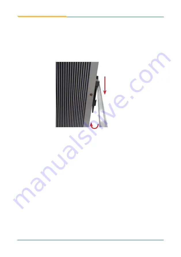
3.4.2. Dismount the Computer

Power off the computer and disconnect all cables before proceeding to dismount the 

computer off the DIN-rail.

1.  Push the top side of the computer down, with both hands. Try to release the clip from 

the DIN-rail.

Push

Lift

2.  Once the clip is released from the DIN-rail, completely dismount the computer off the 

DIN-rail by lifting the computer’s bottom side.

Summary of Contents for AES-5204

Page 1: ...1 AES 5204 Industrial Ethernet Switch with 4x IEEE 802 3at PoE User s Manual Version 1 0 2016 07 P N 4016520400100P...

Page 2: ...2 Revision History Version Release Time Description 1 0 July 2016 Initial release...

Page 3: ...lights 2 1 2 About this Manual 2 1 3 Specifications 2 1 4 Inside the Package 4 1 5 Ordering Information 4 1 5 1 Optional Accessories 4 Chapter 2 Getting Started 5 2 1 Dimensions 6 2 2 Take A Tour 7 2...

Page 4: ...urer Declaration of Conformity CE The CE symbol on the computer indicates that it is in compliance with the directives of the Union European EU ACertificate of Compliance is available by contacting Te...

Page 5: ...ve was published on 2 13 2003 The main purpose of the directive is to prohibit the use of lead mercury cadmium hexavalent chromium polybrominated biphenyls PBB and polybrominated diphenyl ethers PBDE...

Page 6: ...o not place anything over the power cord 8 Never pour any liquid into opening This may cause fire or electrical shock 9 Never open the equipment For safety reasons the equipment should be opened only...

Page 7: ...work on the inside 2 Use a grounded wrist strap when handling computer components 3 Place components on a grounded antistatic pad or on the bag that came with the Box PC whenever components are separ...

Page 8: ...misuse of or inability to use this product Vendor will not be liable for any claim made by any other related party Vendors disclaim all other warranties either expressed or implied including but not...

Page 9: ...1 1 Chapter 1 Introduction Chapter 1 Introduction...

Page 10: ...dling We recommend that you keep one copy of this manual for the quick reference for any necessary maintenance in the future Thank you for choosing ARBOR products 1 3 Specifications System Standard IE...

Page 11: ...Input DC 9 36V input w 3 pin DC input terminal block Power Consumption Max 120W Power Management Vehicle ACC power ignition control Reversed power input protection Ignition controlled power distribut...

Page 12: ...ing items 1 x AES 5204 Industrial Ethernet Switch 1 x User s Manual 1 5 Ordering Information AES 5204 6 port Industrial Ethernet Switch with 4x IEEE 802 3at PoE ports 1 5 1 Optional Accessories The fo...

Page 13: ...5 2 Chapter 2 Getting Started Chapter 2 Getting Started...

Page 14: ...6 Getting Started 2 1 Dimensions The following illustration shows the dimensions of the computer with the measurements in width depth and height called out 155 00 125 00 Unit mm...

Page 15: ...for SFP interface module WAN Port 10 100 1000Base T RJ 45 WAN port PoE LAN Ports 4 x 10 100 1000Base T RJ 45 LAN ports w PoE Compliant with 802 3at output power up to 25 5W per each port Power Termina...

Page 16: ...SFP module is connected Off No SFP module is connected Power LED Green On Power is being supplied to power input Blinking No PoE power is being supplied to power output Off Power is not being supplie...

Page 17: ...9 4 Chapter 3 Installation and Maintenance Chapter 3 Installation and Maintenance...

Page 18: ...assemble the computer 1 Power off your computer and unplug the power cord and any peripherals Place the computer on a flat surface Loosen and remove the 4 screws on each of the side panels and remove...

Page 19: ...the vehicle ignition The pin assignment for the DC power inlet is as below Pin Description Acc 1 2 3 1 DC 9 36V 2 GND 3 ACC ignition signal Follow the instructions below to connect the computer to a...

Page 20: ...to the receptacle on the rear panel ACC DC Mode ACC Mode ACC 3 3 Configuring Power Mode 1 Disassemble the computer to access the system power switch SW1 2 Configure the PIN 4 5 of SW1 according to you...

Page 21: ...ter Follow through the guide below to mount dismount the computer to from a DIN rail 3 4 1 Mount the Computer 1 Find the DIN rail clip on the rear side of the computer as illustrated below Hold the co...

Page 22: ...s before proceeding to dismount the computer off the DIN rail 1 Push the top side of the computer down with both hands Try to release the clip from the DIN rail Push Lift 2 Once the clip is released f...

Reviews: