background image

User’s Manual 


12 

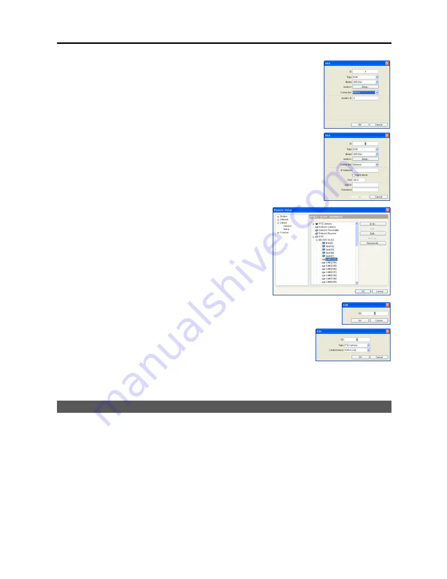
6.2.


Set up the registration information. 

y


ID

: The network keyboard assigns the ID automatically in registration 

order and you can change it.  The ID will be used when controlling the 
device by a network keyboard. 

y


Connection

: Select 

RS485

 or 

Ethernet

 depending on the connections 

to the network keyboard. 


RS485

: Enter the DVR’s system ID preset in the DVR settings when 

the DVR is connected via RS485 connections. 


Ethernet

: Enter the IP address, port number, user ID and password 

for the connection to the DVR when the DVR is connected via RS485 
connections. 


6.3.


Click the 

OK

 button. 


6.4.


Click the DVR pull-down menu in the device list, then the 
registered DVR’s pull-down menu.  A list of monitors and 
cameras connected to the DVR is displayed. 


6.5.


Click a monitor or a camera in the list and click the 

Edit


button. 


6.6.


Set up the monitor or camera information. 

y


ID

: The network keyboard assigns the ID automatically in registration 

order when the DVR is registered and you can change it.  The ID 
will be used when controlling the monitor or camera by a network 
keyboard. 

y


Type

: Set up the camera type. 


Fixed

: Select if the camera is not a PTZ camera. 


PTZ Camera

: Select if the camera is a PTZ camera and set up 

the device that the PTZ camera is connected. 


2.3  Network Matrix System (Transmitter, Receiver and Camera) 

 
You can register network devices including network transmitters, receivers and cameras connected to a 
network keyboard via Ethernet connections.  Only Advanced setup is supported remotely through the INIT 
program. 
 
1.


Connect the network devices to network via Ethernet connections referring to each device’s User’s Manual. 

 
2.


Run the INIT program and connect to the network keyboard to register the devices. 


Summary of Contents for INTELLIGENT NETWORK KEYBOARD

Page 1: ......

Page 2: ......

Page 3: ...E REASONABLE PROTECTION AGAINST HARMFUL INTERFERENCE WHEN THE EQUIPMENT IS OPERATED IN A COMMERCIAL ENVIRONMENT THIS EQUIPMENT GENERATES USES AND CAN RADIATE RADIO FREQUENCY ENERGY AND IF NOT INSTALLED AND USED IN ACCORDANCE WITH THE INSTRUCTION MANUAL MAY CAUSE HARMFUL INTERFERENCE TO RADIO COMMUNICATIONS OPERATION OF THIS EQUIPMENT IN A RESIDENTIAL AREA IS LIKELY TO CAUSE HARMFUL INTERFERENCE IN...

Page 4: ...e equipment exhibits a distinct change in performance this indicates a need for service 14 Replacement Parts When replacement parts are required be sure the service technician has used replacement parts specified by the manufacturer or that have the same characteristics as the original part Unauthorized substitutions may result in fire electric shock or other hazards 15 Safety Check Upon completio...

Page 5: ...17 3 2 Operation Commands 17 3 3 PTZ Camera 18 PTZ Camera Control 18 3 4 DVR System 18 PTZ Camera Control 19 DVR Control on Main Monitor 19 DVR Control on Monitor Advanced Setup Installation Only 19 3 5 Network Matrix System Transmitter Receiver and Camera 19 PTZ Camera Control 20 Camera Control on Main Monitor 20 Camera Control on Pane 20 3 6 MMX System 21 PTZ Camera Control 21 DVR Control on Mai...

Page 6: ... General 27 Button 28 LCD 28 Audio 29 5 2 Network 29 IP Address 29 DVRNS 29 5 3 Device 30 General 30 Setup 31 5 4 Function 32 Macro 32 Button 33 Appendix 35 Troubleshooting 35 Connector Pin Outs 35 Front Panel Buttons 35 PTZ Camera Model Number 38 Specifications 39 ...

Page 7: ...d network cameras via RS485 or Ethernet connections y Remote control of various models of PTZ cameras via network connections y Two way audio communication y Convenient firmware upgrades via either the USB port or Ethernet y Firmware duplication and autorecovery functions to enhance system stability y Management of multiple network keyboards via Ethernet connections y Recalls of maximum 100 macros...

Page 8: ...nufacturer s manual for configuring the RS485 connection 7 Power In Connect the power adaptor to the network keyboard The network keyboard starts booting as soon as power is applied 8 Joystick Connect a joystick cable to the network keyboard NOTES y The network keyboard does not have amplified audio output so you will need a speaker with an amplifier y Audio surveillance may be prohibited by laws ...

Page 9: ...onnect the joystick cable Factory Reset This switch will only be used on the rare occasions that you want to return all the settings to the original factory settings CAUTION When performing a Factory Reset you will lose any settings you have saved You can perform a factory reset while the network keyboard is turned on Poke a straightened paperclip into the factory reset switch hole and hold the sw...

Page 10: ... next image and pressing the button moves to the previous image 6 Enter Button Pressing the Enter button selects an item or completes an entry that you have made during the LCD setup In the live monitoring mode pressing the button freezes the current screen When in the playback mode pressing the button pauses playing video 7 Command Control Buttons Commands the preset action See Chapter 3 Operatio...

Page 11: ...d joystick are provided for the PTZ control See Chapter 2 PTZ Camera p 9 section for details of the connections DVR System RS485 Connection 9 You can control DVRs directly connected to a network keyboard via RS485 connections The live or playback video is displayed on the main monitor connected to each DVR See Chapter 2 DVR System p 10 section for details of the connections ...

Page 12: ...change camera channels on the monitor remotely See Chapter 2 DVR System p 10 section for details of the connections Network Matrix System Network Transmitter Receiver and Camera 9 You can build a virtual matrix system with network transmitters network receivers and network cameras via Ethernet connections See Chapter 2 Network Matrix System Transmitter Receiver and Camera p 12 section for details ...

Page 13: ...ystem with MMXs and DVRs and control live monitoring and playback on the main and spot monitors by a network keyboard via Ethernet connections You also can control PTZ cameras connected to DVRs See Chapter 2 MMX System p 14 section for details of the connections ...

Page 14: ...User s Manual 8 ...

Page 15: ... in the Basic setup locally through the LCD setup menus or remotely through the INIT program See Chapter 5 Remote Configuration 5 3 Device for details on the remote registration through the INIT program 1 Connect PTZ cameras to RS485 PTZ port of the network keyboard referring to the PTZ camera s User s Manual 2 Enter the LCD setup menu See Chapter 4 LCD Menu Configuration for details on entering a...

Page 16: ...ctions of any devices while the Advanced setup support both RS485 connections and Ethernet connections Basic Setup DVRs can be registered on the network keyboard in the Basic setup locally through the LCD setup menus or remotely through the INIT program See Chapter 5 Remote Configuration 5 3 Device for details on the remote registration through the INIT program 1 Connect DVRs to RS485 DVR port of ...

Page 17: ...nect DVRs to the RS485 DVR port of the network keyboard via RS485 connections or to the network via Ethernet connections referring to the DVR s User s Manual 2 Connect the network keyboard to network via Ethernet connections See Chapter 1 Rear Panel 3 Run the INIT program and connect to the network keyboard to register the DVRs 4 Go to the following menus Setup Remote Setup Network IP Address Set ...

Page 18: ...lick a monitor or a camera in the list and click the Edit button 6 6 Set up the monitor or camera information y ID The network keyboard assigns the ID automatically in registration order when the DVR is registered and you can change it The ID will be used when controlling the monitor or camera by a network keyboard y Type Set up the camera type Fixed Select if the camera is not a PTZ camera PTZ Ca...

Page 19: ...and cameras in a LAN environment Checking the boxes of devices to register and clicking the Add button allows you to register more than one device at a time on the network keyboard You can find a specific device by entering the network information and by clicking the Manual Scan button when the device is not listed up Click the Add button to register the device on the network keyboard 5 2 Set up t...

Page 20: ...t for selecting a pane during operation Pressing a pane ID and the PANE button is the same as pressing a monitor ID and the MON and then a pane number and PANE button y Type Set up the camera type Fixed Select if the camera is not a PTZ camera PTZ Camera Select if the camera is a PTZ camera and set up the device that the PTZ camera is connected 2 4 MMX System You can register MMXs connected to a n...

Page 21: ... the MMX 5 3 Click the OK button 5 4 Click the DVR pull down menu in the device list then the registered DVR s pull down menu A list of monitors and cameras connected to the DVR is displayed y Main ID Indicates the ID of the main monitor connected to the DVR y Spot No ID Indicates the Spot out number and ID of the spot monitor connected to the DVR y CAM No ID Indicates the Video In number of the D...

Page 22: ...ot Out number of the spot MMX and spot monitor ID y M CAM No ID Indicates the Video In number and ID of the camera connected to the MMX M master MMX S1 slave MMX 1 6 3 Click a monitor or a camera in the list and click the Edit button 6 4 Set up the monitor or camera s ID The network keyboard assigns the ID automatically in registration order when the MMX is registered and you can change it The ID ...

Page 23: ...you to control the device including playback and menu setup 9 Commands on LCD screen indicates as follows A capital letter C Indicates the camera ID which is a user defined camera number to distinguish the camera from others when controlling the camera by the network keyboard A small letter c Indicates the camera number which is a Video In number of the DVR that the camera is connected A capital l...

Page 24: ...Macro No y Action Selects a macro to perform y Action Moves to the previous or next menu during setting menu or selects the previous or next camera pane monitor device or macro Function 1 to 8 y Action Performs preset macro 5 to 8 1 to 4 SHIFT 3 3 PTZ Camera You can control PTZ cameras connected to the network keyboard by a network keyboard via RS485 connection PTZ Camera Control 1 Press the PTZ c...

Page 25: ...onitor connected to the DVR and you can control the camera if the camera is a PTZ camera by using the PTZ control buttons and joystick DVR Control on Monitor Advanced Setup Installation Only 1 Press the main monitor s ID 2 Press the MON button If the selected monitor is a main monitor you can control the DVR on the main monitor by using the device control buttons arrow button jog dial and shuttle ...

Page 26: ...nected 3 Press the camera ID 4 Press the CAM button Video from the user defined camera is displayed on the main monitor and you can control the camera if the camera is a PTZ camera by using the PTZ control buttons and joystick Camera Control on Pane 1 Press the monitor ID 2 Press the MON button You can control the network device that the selected monitor is connected 3 Press the pane number 4 Pres...

Page 27: ...ess the DVR ID 4 Press the DEV button You can control the DVR on the main monitor by using the device control buttons arrow button jog dial and shuttle ring 5 Press the camera number of the DVR 6 Video from the selected camera is displayed on the main monitor connected to the DVR and you can control the camera if the camera is a PTZ camera by using the PTZ control buttons and joystick Camera Contr...

Page 28: ...ons arrow button jog dial and shuttle ring 7 Press the camera number of the DVR 8 Press the CAM button Video from the selected camera is displayed in the selected pane on the main monitor connected to the DVR and you can control the camera if the camera is a PTZ camera by using the PTZ control buttons and joystick Example II When the pain ID is set up for a main monitor connected to the MMX in Rem...

Page 29: ...Pane Example I You can control cameras in the selected pane on the main monitor 1 Press the monitor ID 2 Press the MON button You can control the main monitor 3 Press the pane number 4 Press the PANE button 5 Press the camera ID 6 Press the CAM button Video from the user defined camera is displayed in the selected pane on the main monitor connected to the DVR and you can control the camera if the ...

Page 30: ...on You can control the main monitor 3 Press the camera ID 4 Press the CAM button Video from the user defined camera is displayed in the user defined pane and you can control the camera if the camera is a PTZ camera by using the PTZ control buttons and joystick ...

Page 31: ...t setting Pressing the button until the screen displays Save Setup allows you to save or cancel the changes y 0 to 9 Enters a number value 0 to 999 y SHIFT Enters the LCD setup menu when pressing the button together with the button y Enters the LCD setup menu when pressing the button together with the SHIFT button goes to the submenu selects an item or completes an entry that you have made y Moves...

Page 32: ...1 Low 2 Medium 3 High Backlight Off Allows you to enter the backlight expiration time min of the LCD screen This function does not work if the time is set to 0 Audio Volume Allows you to enter the volume of audio input and output Upgrade Setting the value to Yes upgrades the software Device General Setup Type Allows you to select the setup type Select Basic for RS485 connection The Advanced type i...

Page 33: ... not available for the remote setup Clicking a menu in the left of the Remote Setup screen displays the current settings for that menu on the right side of the screen Clicking submenus under each menu allows you to change the settings Clicking the OK button closes the Remote Setup screen and applies the changes 5 1 System You can change system information import or export all setting values change...

Page 34: ... you to select the setup file You can select whether or not network settings IP address port number DVRNS will be included when the setup is applied Export Setup Click to save the current network keyboard settings as a dat file format A setup screen appears allowing you to name the setup file Button y Beep Check the box to make a sound when pressing buttons on the front panel of the network keyboa...

Page 35: ...he OK button and a temporary IP address is automatically assigned to the network keyboard The network keyboard periodically will be issued a new IP address automatically y DNS Server Enter the IP address of the DNS server If you set up the DNS server the domain name of the server can be used instead of the IP address when the DVRNS server is set up Ask your Internet service provider for the IP Add...

Page 36: ...r RS485 connection only or Advanced for Ethernet and RS485 connection depending on the device s connection type to the network keyboard Port Select the device from the drop down list to set up port numbers separately for the RS485 communication between PTZ cameras and the network keyboard or DVRs and the network keyboard The settings applied to all devices in the Basic setup type and the RS485 com...

Page 37: ...o the device and clicking the Edit button allows you to change the information including an ID of the monitor or camera Assigning a pane ID to each pane in the main monitor allows you to control the user defined pane with a unique pane ID Four channel network receiver and MMX only y Remove Remove All Select a device in the list and click the Remove button to delete it Clicking the Remove All butto...

Page 38: ... the number of spot monitors connected to spot MMXs Connection Select the device s connection type to the network keyboard and configure the settings When a DVR is connected to the network keyboard via RS485 connection you will be asked to enter the system ID assigned to the DVR during the DVR setting 5 4 Function You can register more than 100 macros on eight function buttons for quick action Mac...

Page 39: ... field and click a button to perform on the front panel image in the left Dwell Time Enter dwell time second for the action to last Button y Button Displays the function on the front panel y Macro No Assign the macro number to be associated with the function button Pressing the function button on the front panel of the network keyboard performs the preset macro ...

Page 40: ...User s Manual 34 ...

Page 41: ... settings to the original factory settings You must customize all settings including network settings after a factory reset Connector Pin Outs RS485 Connector Master Unit Slave Unit To TX RX To TX RX Front Panel Buttons PTZ Camera Control Depending on the PTZ camera specifications some features may not work Refer to the PTZ camera manufacturer s manual for details of each feature Button Designatio...

Page 42: ... devices of the selected device Display Cameo y Buttons Layout No Display or SHIFT Cameo y Action Changes screen layout 1 full 2 2x2 3 3 3 4 3x3 5 2 8 6 1 12 7 4x4 8 PIP 9 1 5 10 1 12 or enters cameo mode The screen layout number is defined by user s setting if the device is a MMX Pressing the button without pressing a layout number changes screen layout according to the DVR s screen layout Group ...

Page 43: ... video Arrow Buttons y Action Allows you to navigate through menus and GUI of the device when controlling a device by a network keyboard They also are used to control Pan and Tilt when in the PTZ mode In the playback mode pressing the and plays video backward and forward When in the pause mode pressing the button moves to the next image and pressing the button moves to the previous image Jog Dial ...

Page 44: ...ller Dongyang 27 CDC2400 DynaColor 28 Ultra VI Sensormatic 29 ZC SD622J CBC 30 Siemens SCU Siemens 31 PTC 200C CVAS ELMO 32 DRX 500 Dongyang Unitech 33 GHSD 7425 Series GSP 34 GHSD 7344 Series GSP 35 GHSD 7448 Series GSP 36 VisionDome 360Vision 37 Vicon Vicon 38 HSDN 251 Honeywell 39 HDC 655 Honeywell 40 Pacom 2036 Pacom 41 CDC 2500 Costar 42 VRX 2201 Inter M 43 DY 255RXC Dongyang 44 VC C50i Canon...

Page 45: ...485 DVR Serial Port Terminal block USB Port 2 on back panel 2 0 GENERAL Dimensions W x H x D 14 8 x 3 7 x 70 0 376 9mm x 95mm x 177 6mm Shipping Dimensions W x H x D 179 1 x 63 0 x 100 4 455mm x 160mm x 255mm Unit Weight 2 41 lbs 1 1Kg Shipping Weight 4 71 lbs 2 1Kg Operating Temperature 32 F to 122 F 0 C to 50 C Operating Humidity 0 to 90 Power Supply 5 VDC 3A Power Consumption Max 6W Approval FC...

Reviews: