background image

PY500AC SLIDING GATE OPERATOR

2

1.

1.

1.

1. Products

Products

Products

Products introduction

introduction

introduction

introduction

please

please

please

please read

read

read

read the

the

the

the instructions

instructions

instructions

instructions carefully

carefully

carefully

carefully before

before

before

before proceeding.

proceeding.

proceeding.

proceeding.

MCU

MCU

MCU

MCU is

is

is

is supplied

supplied

supplied

supplied to

to

to

to control

control

control

control the

the

the

the gate

gate

gate

gate operator.

operator.

operator.

operator.

Keypad

Keypad

Keypad

Keypad //// single

single

single

single button

button

button

button interface.

interface.

interface.

interface.

P

P

P

Photo

hoto

hoto

hoto beam

beam

beam

beam safety

safety

safety

safety beam

beam

beam

beam interface.

interface.

interface.

interface.

User

User

User

User can

can

can

can select

select

select

select Auto-close

Auto-close

Auto-close

Auto-close function.

function.

function.

function.

Manual

Manual

Manual

Manual key

key

key

key release

release

release

release design

design

design

design for

for

for

for emergency

emergency

emergency

emergency purposes.

purposes.

purposes.

purposes.

Gate

Gate

Gate

Gate operator

operator

operator

operator has

has

has

has a

a

a

auto

uto

uto

uto-reverse

-reverse

-reverse

-reverse function,

function,

function,

function, and

and

and

and the

the

the

the reverse

reverse

reverse

reverse power

power

power

power can

can

can

can change

change

change

change by

by

by

by user.

user.

user.

user.

2.

2.

2.

2. Important

Important

Important

Important safety

safety

safety

safety information

information

information

information

Carefully read and follow all safety precautions and warning before attempting to install and use this

automatic gate operator.

Make

Make

Make

Make sure

sure

sure

sure the

the

the

the Power

Power

Power

Power supply(AC220V

supply(AC220V

supply(AC220V

supply(AC220V or

or

or

or AC110V)

AC110V)

AC110V)

AC110V) of

of

of

of the

the

the

the gate

gate

gate

gate operator

operator

operator

operator is

is

is

is suitable

suitable

suitable

suitable for

for

for

for the

the

the

the power

power

power

power

supply

supply

supply

supply in

in

in

in your

your

your

your area.

area.

area.

area.

3.

3.

3.

3. Main

Main

Main

Main technical

technical

technical

technical parameters

parameters

parameters

parameters

4.

4.

4.

4. Mechanical

Mechanical

Mechanical

Mechanical Installation

Installation

Installation

Installation

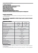
The PY500AC will handle gate weighting up to 500kg and up to 12m if the proper installation procedures

have been followed.

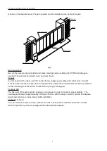
The PY500AC gate operator operates by forcing a drive rack by a drive gear.

The entire configuration

Type

PY500AC

PY500ACU

Power supply

220V, 50Hz

110V, 60Hz

Motor speed

42rpm

47rpm

Rated output power of motor

150W

Remote control operating distance

30m (Frequency: 433.92mHz)

Remote control mode

Single button

Output shaft height

58.5mm

Max. gate weight

500Kg

Output torque

14N

·

m

Limit switch

Spring limit switch

Noise

60dB

Duty cycle

S2, 15 minutes

extra remote control

100

Environmental temperature

-20°C~+50°C

Gate Move speed

12m/min

Summary of Contents for PY500AC

Page 1: ...Sliding Gate Operator User s Manual PY PY PY PY5 5 5 500 00 00 00A A A AC C C C...

Page 2: ...introduction 2 2 Important safety precautions 2 3 Main technical parameters 2 4 Mechanical Installation 2 5 Adjustment 5 6 Wire Connecting 6 7 Turning and operation 8 8 Programming Process 10 9 Mainte...

Page 3: ...ange change change by by by by user user user user 2 2 2 2 Important Important Important Important safety safety safety safety information information information information Carefully read and follow...

Page 4: ...ntrol wires Conduit must be preset into the concrete when it is poured Wires within the conduit shall be located or protected so that no damage can result from contact with any rough or sharp part Con...

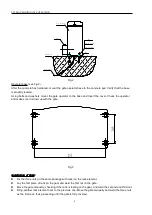
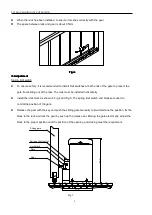
Page 5: ...operator and make sure it is lined up with the gate Fig 3 Installation Installation Installation Installation of of of of Rack Rack Rack Rack Fix the three nuts in the same package with rack on the ra...

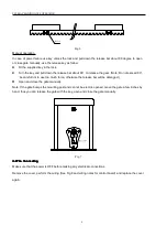
Page 6: ...ing out of the rails The rails must be installed horizontally Install the limit block as shown in Fig 4 and Fig 5 The spring limit switch and blocks are used to control the position of the gate Releas...

Page 7: ...reful not to use too much force otherwise the release bar will be damaged Open and close the gate manually Note If the gate bumps the mounting post and cannot be electric opened move the gate a few in...

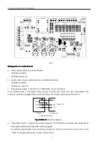
Page 8: ...uring closing the gate will reverse and open immediately The product is not factory equipped with an infrared device the infrared output signal must be N C GND 12V Out I R COM 12V Terminal X2 Infrared...

Page 9: ...W Terminal X7 E W Control board Terminal X6 C C Capacitor V U V U Fig 11 7 7 7 7 Tuning Tuning Tuning Tuning and and and and operation operation operation operation Remote control The remote control...

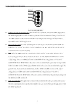
Page 10: ...control button which has been learned the gate will open the motor rotates clockwise and the LED3 and LED4 is turns on The output voltage between LAMP terminal X4 is AC220V 110V the voltage between V...

Page 11: ...close auto close auto close auto close function function function function has been set Cancel auto close function Turn on the second and the third DIP switch see Fig 8 to ON position Press the remote...

Page 12: ...g to your requirements 1 44 sec this period of time is regarded as auto close time of pedestrian mode Close the gate by pressing the same button button 4 Press the same button again to stop the gate o...

Page 13: ...uto close function of pedestrian mode has been canceled Note the new width of pedestrian mode has been re programmed in the device and replaced the original width If you open the gate with button 4 th...

Page 14: ...mode mode external external external external button button button button switch switch switch switch keypad keypad keypad keypad not not not not supply supply supply supply With each press of the but...

Page 15: ...gn and specification without prior notification 10 10 10 10 Troubleshooting Troubleshooting Troubleshooting Troubleshooting 11 11 11 11 Packing Packing Packing Packing list list list list After receiv...

Reviews: