Rev B
37
4. TROUBLESHOOTING AND REPAIR
4.1 GENERAL
Because it is a relatively simple instrument, the Model 2000W1000D should require very little maintenance.
It is built with solid state devices and printed wiring boards (PWBs) that should ensure long, trouble-free life.
Should trouble occur, special care must be taken when servicing the unit to avoid damaging the solid state
devices and PWB’s.
Since the amplifier’s components are soldered in place, substitution of components should not be resorted to
unless there is some indication that they are faulty. In addition, care must be taken not to short voltages
across the amplifier when troubleshooting, because small bias changes may damage the amplifier due to
excessive dissipation or transients.
Components used in AR RF/Microwave Instrumentation instruments are conservatively operated to provide
maximum instrument reliability. In spite of this, parts may fail. Usually, the instrument must be immediately
repaired with a minimum of down time. A systematic approach can greatly simplify and thereby speed up
repairs. The Model 2000W1000D incorporates fault control and detection circuits, including display panel
indications that can expedite troubleshooting of the unit. For a description of how these indications can be
used to assist in troubleshooting the unit, please see Section 4.3,
Fault Signal Interpretation and
Diagnosis.
Shipping instructions are as follows. To return an item, contact AR Customer Service for an RMA number
and shipping instructions. Returns from outside the United States are not permitted without prior
authorization. If shipping from outside of the United States, closely follow all directions on the RMA form
for return shipping and marking. See warranty statement at rear of manual.
4.3 FAULT SIGNAL INTERPRETATION AND DIAGNOSIS
CAUTION:
Extreme caution should be exercised when troubleshooting this unit,
particularly when measuring voltages in the power supply section, as
hazardous voltages exist in the unit that could cause serious injury to
personnel performing such measurements.
4.3.1
General - Reading Faults
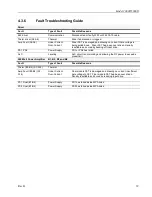
The Model 2000W1000D incorporates relatively simple fault detection circuitry, which makes use of the
digital display panel to alert the user or technician which component(s) need service. Use of these indications
can usually expedite troubleshooting of the amplifier. Most faults can be immediately determined down to
the assembly level. If a reset is still indicated, turn off the RF power signal to the input of the amplifier, read
and record the fault indication displayed on the digital control panel for later reference. Then, use the
RESET
function
to see if the fault clears. If the fault clears, slowly bring the amplifier’s drive level back up and
ensure that recommended RF power levels are not exceeded. If the fault indication is no longer visible, the
fault may have been brought about by a temporary transient condition, component thermal condition or
excessive RF drive to the amplifier’s input. If the fault does not clear with the RF drive off, some other
problem exists in the amplifier.
Summary of Contents for 2000W1000D
Page 2: ......
Page 4: ......
Page 6: ......
Page 18: ......
Page 40: ...Model 2000W1000D 30 Rev B ...
Page 46: ...Model 2000W1000D 36 Rev B ...
Page 52: ......
Page 54: ......


