background image

AT-MZA


Multi Zone Alarm

LEAK DETECTION SOLUTIONS

Weights & Measures House, 20 Barttelot Road, 
Horsham, West Sussex RH12 1DQ

+44 (0) 1403 216100

[email protected]

www.aquilar.co.uk

NORMAL MODE INDICATIONS:

LEAK LED (Red) 


OFF

CABLE BREAK LED (Yellow)   ON
POWER LED ON (Green)  

ON

ALARM/TROUBLE RELAY 

NORMAL (de-enrgised)

LEAK MODE INDICATIONS:

LEAK LED (Red) 


ON

CABLE BREAK LED (Yellow)   OFF
POWER LED ON (Green)  

ON

ALARM/TROUBLE RELAY 

ALARM(enrgised)

USER ACTION

1. Locate the spill area, investigate the cause of the spill and take necessary repair actions.
2. Clean up in the spill area and clean and dry the cable / probe, if necessary. LEAK LED will turn 

off when cable / probe is dried.

CABLE BREAK INDICATIONS:

LEAK LED (Red) 


OFF

CABLE BREAK LED (Yellow)   ON
POWER LED ON (Green)  

ON

ALARM/TROUBLE RELAY 

ALARM(enrgised)

USER ACTION

1. Investigate the sensor cable and leader cable for physical damage. Check connectors for 

damage. Make repairs or replace components as necessary.

2. 

CABLE BREAK LED automatically turns off when normal sensor cable continuity is restored.

The Alarm Relay automatically returns to the NORMAL position when cable continuity is 
restored.

12

Summary of Contents for AquiTron AT-MZA

Page 1: ...AT MZA Multi Zone Alarm AquiTron INSTALLATION INSTRUCTIONS...

Page 2: ...n Class I Division 2 Groups A B C D Hazardous Locations If protected by agency approved zener barrier TraceTek sensing cable in Class I Division 1 Groups A B C D Hazardous Locations Zone 0 or Zone 1 i...

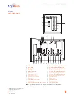
Page 3: ...14 Z1 2 Leak relay cable plug and socket 15 Z1 2 Sensing cable plug and socket 16 Z3 4 Leak relay cable plug and socket 17 Z3 4 Se nsing cable plug and socket 18 Z5 6 Leak relay cable plug and socket...

Page 4: ...sure to static electricity Avoid contamination with metal filings liquids or other foreign matter Remove the module from its packaging Open the enclosure door using a flat blade screwdriver or coin An...

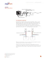
Page 5: ...ur coded wires to the Sensor Interface plug X3 X7 X10 and X12 see Fig 4 SENSOR RED GR N YEL BLK x3 x7 x10 x12 Select a spare connector between zones 1 to 8 Zones 1 2 do not require the insertion of a...

Page 6: ...an 3 amps via an un switched fused spur adjacent to the unit Note Do not exceed maximum voltage The unit is equipped with a 12Vdc battery back up power circuit If this option is required connect the a...

Page 7: ...nical damage Keep the electronics dry If handling circuit boards hold them by their edges to avoid physical contact with electronic components Avoid exposure to static electricity Avoid contamination...

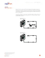
Page 8: ...terminals So to operate a valve for example you need to have a dedicated power supply which is then fed through the relay typically the live feed to switch it on or off accordingly Typical wiring is a...

Page 9: ...a plan showing the location of the sensor is available 3 Check that the following information is clearly visible adjacent to the alarm module In case of alarm instruction Location of the system map in...

Page 10: ...portion of the system to verify circuit integrity to detect the presence of liquid and even to determine its location as the PTB will give you an indication in feet or metres to the point of the leak...

Page 11: ...older or weld near the cable without providing protection from heat solder flux or weld splatter Do not drop tools or floor tiles on the cable sharp and heavy objects may damage the cable Avoid walkin...

Page 12: ...ssary or insert a small piece of insulating material to prevent the cable from making contact with the metal edge Problem Leak Alarm but no leak is found Possible Cause Cable is pinched all cables Act...

Page 13: ...nvestigate the cause of the spill and take necessary repair actions 2 Clean up in the spill area and clean and dry the cable probe if necessary LEAK LED will turn off when cable probe is dried CABLE B...

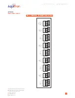
Page 14: ...ar co uk 13 FIG 8 TERMINAL CONNECTION LAYOUT SENSO R RED GR N YEL BL K Z8 x3 Z7 N O CO M N C LEAK REL AY x5 SENSO R RED GR N YEL BL K Z6 x7 Z5 SENSO R RED GR N YEL BL K Z4 x10 Z3 SENSOR RED GR N YEL B...

Page 15: ...be liable for any incidental indirect or consequential damages arising from the sale resale use or misuse of the product Specifications are subject to change without notice In addition Aquilar Limite...

Reviews: