background image

16

14

12

10

8

6

4

2

KEY's Storage

Location

c

alibrate


the

 f

low

 r

ate

Calibrated Flow Rate

Means having a (set) specific flow rate when the Flow Control Valve is 

fully open. This allows for an easy repeat of fogging operations.

Also, the flow rate can be calibrated to match with a chemical's 

dilution ratio. An important feature when using a metering pump.

To Calibrate a Flow Rate 

(Two Techniques)

Fill the tank with some water.

T1) 

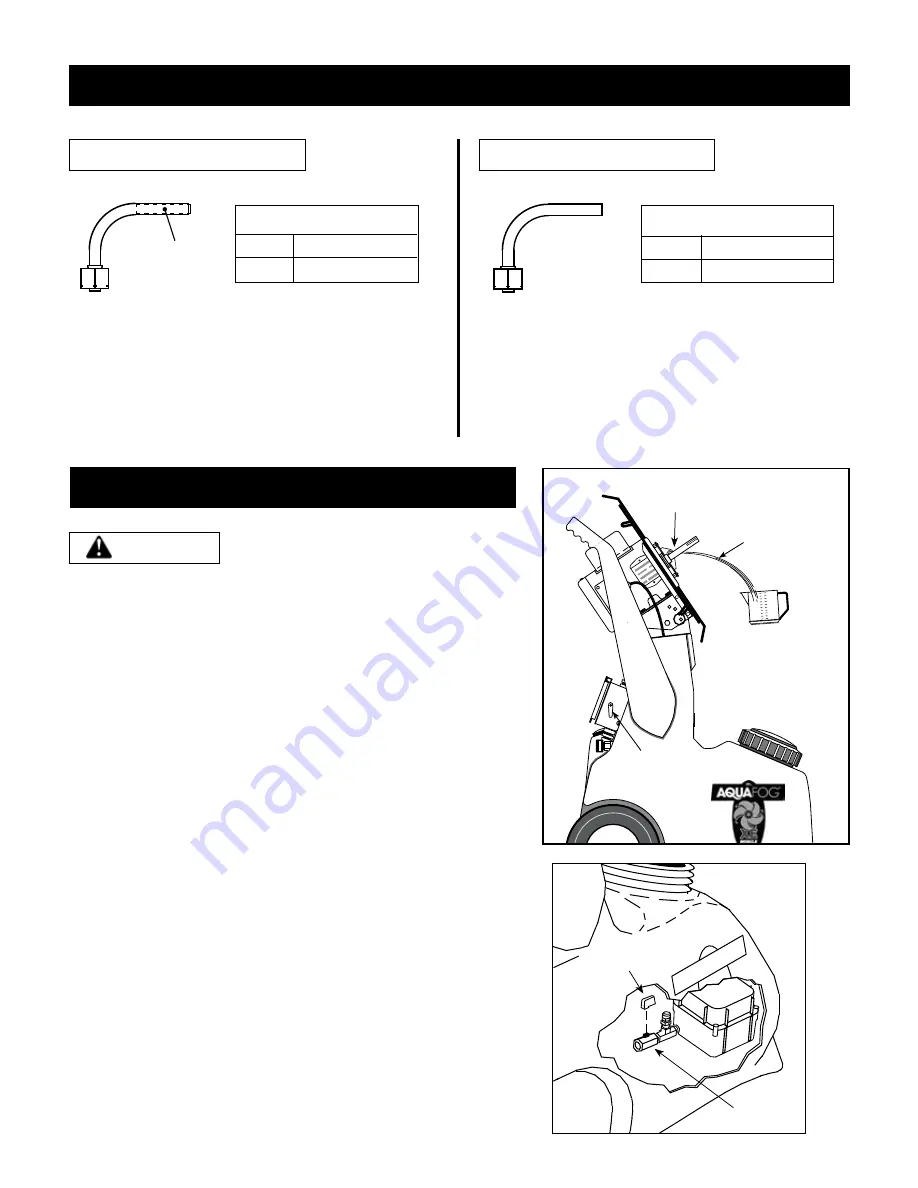
Carefully remove the housing's drain tubing from the tank.


Tilting the fogging head temporarily, will ease removal. 


  [or]

T2)

  Remove the Fan Housing and Blade Assembly to expose the  

        Feed Tube (See 

Fig. 3

). This will allow a visual of the


water stream, helpful when making adjustments.

Fully open the Flow Control Valve located on the back of the unit. 

Only turn on the feed pump (lower switch). Use a measuring cup 

to catch water in 60 second intervals from the Feed Tube or Drain 

Tubing. Multiply ounces of water by 60 and then divide by 128. This 

will give you your GPH rate. Use the Key on the internal valve to make 

adjustments and repeat process as needed (see below).
 

Math example: 1 minute captures (4.2 ozs. x 60 ÷ 128 = 2 GPH)

The valve KEY is needed to make changes

You will need the KEY located on the side of the electrical control box 

to make changes (see 

Fig. 3

). Slide this key on top of the flow valve's 

stem (see 

Fig. 4

) to make your adjustment.

After calibration remove handle to safeguard the flow rate.

Fig. 3

AUTOMATIC PRIMING OF THE SYSTEM 

OCCURS THROUGH THE FLOW RATE VALVE. 

NOTICE

f

low

 r

ates

6

M

AQU

AFOG

Flow Rate

Valve KEY

Fig. 4

Capture & Measure 

Water Output

Feed Tube

LOW FLOW, Feed Tube

Colored

Insert

HIGH FLOW, Feed Tube

Low Flow Tube (factory installed)

The Low Flow tube is more accurate, reliable and easier 

to adjust at low flow rates.
It can be identified by its colored insert.

High Flow Tube (provided)

To install the high flow tube, first disconnect power. 

Then gain access to the feed tube location by removing 

the housing and fan blade assembly (see Fig. 3). 

Replace tube, maintaining the same angle of the tube 

installed by the factory.

Output Range:

@  60Hz      .75  -  3.75      GPH
@  50Hz      2.8  -  14.0      LPH

Output Range:

@  60Hz      3.0 -  11.25      GPH
@  50Hz      7.6  -  31.2         LPH

Every

2.13 ozs per 

minute = 1 GPH

Caibrate 

Flow Rate

Summary of Contents for XE ORSM

Page 1: ...derstand Retain for Future Reference XE MOBILE ATOMIZER USER S MANUAL AND OPERATING INSTRUCTIONS OPERATOR S MANUAL NOTICE Rear Feed UL and CSA Electrical Components XE ORSM MODEL 115V 60Hz 1Ph 240V 50...

Page 2: ...afety guidelines DANGER DANGER INDICATES AN IMMINENTLY HAZARDOUS SITUATION WHICH IF NOT AVOIDED WILL RESULT IN DEATH OR SERIOUS INJURY WARNING INDICATES A POTENTIALLY HAZARDOUS SITUATION WHICH IF NOT...

Page 3: ...h use inspect blade assembly andelectricalcomponentsforsignsofdamage deterioration weakness or leakage Repair or replace defective items before using 10 Check all fasteners at frequent intervals for p...

Page 4: ...0 ft 115 230 16 AWG 14 AWG Fig 12 Electrical GROUND FAULT RECEPTACLES ARE RECOMMENDED AND MAY BE REQUIRED BY LOCAL AND OR NATIONAL CODE WARNING USE OF AN EXTENSION CORD IS NOT RECOMMENDED IF NECESSARY...

Page 5: ...puts for short periods of time At the base of the plumbing is an in line strainer with a removable cap Occasionally check inside and flush any sediment from the screen The Hose Connection is used to s...

Page 6: ...he internal valve to make adjustments and repeat process as needed see below Math example 1 minute captures 4 2 ozs x 60 128 2 GPH The valve KEY is needed to make changes You will need the KEY located...

Page 7: ...d poor inconsistent fogging output D Consistency of fogging output greatly depends on the consistency of the cleaning procedures See Page 10 Check strainer plumbing and inside of tank for dried sedime...

Page 8: ...betweenthemotorshaftandthestainlesssteelfaceplate Centeredintheslotareaand aimed slightly downward free from any rotational contact B Liquid not traveling through the fan blades This can be diagnosed...

Page 9: ...ST 8 58 5 16 flat washer SST 12 114 Drain fitting nut 1 115 Drain gasket 1 116 5 16 18 finish nut SST 4 117 1 4 20 x 5 8 HH bolt SST 4 308 XE blade tip setscrew SST 3 349 5 16 brass rod 1 391 Top pivo...

Page 10: ...Side of top pivot plate Rear of Housing To feed pump 14 16 52 600 L 117 54 20 49 58 56 32 58 57 56 57 116 349 403 391 392 56 394 395 32 479 20 600 R Motor s Junction Box 576 7 523 522 35 From Switch B...

Page 11: ...61 84 45 71 72 65 65 295 295 W 14 65 65 84 45 198 67 65 Tank s Wall Inside Tank ORSM Tank Exploded View 232 207 86 423 423 75 171 173 143 3 8 tube fitting provided for optional connection to metering...

Page 12: ...2 86 6 32 x 1 2 oval slotted screw 6 93 Hose connector gasket 1 94 Hose connector 1 96 Gasket 2 97 Float valve 1 98 Stem 1 99 Float 1 111 Axle SST 1 126 1 4 lockwasher SST 2 143 1 4 NPT M X 3 8 tube...

Page 13: ...t once a year or whenever a film of calcium or mineral deposits is visible While cleaning inspect for irregularities or hairline cracks and replace as necessary 5 Storage Protect your mobile Aquafog f...

Page 14: ...ck of maintenance or unauthorized repairs or alterations which affect the machine s performance or reliability LIMITATIONS OF LIABILITY TO THE EXTENT ALLOWABLE UNDER APPLICABLE LAW JAYBIRD MANUFACTURI...

Reviews: