background image

9

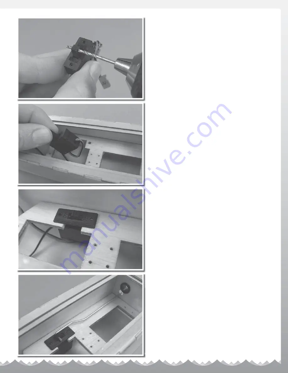
Use a 5/64" drill bit to enlarge the hole in the 
switch for the ON/OFF switch pushrod.

Slip the switch (ON facing to the front of the 
boat) through the throttle servo opening.

Place the switch plate in place.

Slide the ON/OFF pushrod in the box, positioning the 
hook in the end of the wire through the switch. It is 
best to install the wire through the hole in the switch 
from the box side so it cannot fall out during use.

Summary of Contents for TOP SPEED3

Page 1: ...n boat or duck boat NOTE Because of the sharp running hardware included with this RC boat we do not recommend a rubber blow up raft RC boat running hardware is very sharp Be very careful when working on and around the metal parts While the engine is running pay close attention to the propeller Do not come in contact with the propeller at any time the engine is running or serious injury will result...

Page 2: ...r that has multiple model memory allowing you to easily grow as your racing program grows 1 FUTK2021 Futaba 3PM X Radio system less servos 1 FUTM0031 Futaba 3003 Standard Servo Throttle 1 FUTM0102 Futaba S9402 High Speed Coreless BB Steering 3 FUGP7300 Fuji AA batteries 4 pack OPTION 3 This option costs the most money and is top of the line equipment 1 FUTK4900 Futaba 4PK Radio system less servos ...

Page 3: ...ur TS3 should happen to stall water currents will slowly carry it to shore The bad news is that the boat could be carried to the opposite shore When surveying areas to run your model keep variables in mind such as wind direction size of the lake etc It is not advisable to run R C boats on any free flowing bodies of water such as creeks or rivers WARRANTY SERVICE AquaCraft will warrant your model f...

Page 4: ... 2 lengths side to side Glue the Ts to the ends of the tubing making sure the Ts are parallel to each other Join the completed parts together using the short 2 lengths of piping You will have to work fast as the cement sets the parts almost instantly SETUP BOARD Your setup board is going to be a very important tool in getting your boat to perform at its best Here is a simple how to Using MDF or co...

Page 5: ...ead locker on the screw to help secure the parts Now is also a good time to check the direction of the mount plate to make sure it s positioned with the pivot boss near the bottom You can also install the throttle cable clamp at this time FOR THIS STEP YOU ARE GOING TO NEED Scissors or hobby knife Hand drill with both 1 8 and 9 64 drill bits 2 5mm hex wrench Masking tape Cut engine mounting templa...

Page 6: ...he 3mm bolts and washers supplied in the kit Don t worry about setting the engine height at this time as we will get to that during the setup part of the manual FOR THIS STEP YOU ARE GOING TO NEED Medium CA glue or 12 minute epoxy Hand drill with 1 16 drill bit 1 Phillips screwdriver Glue the fuel tank tray together Waterproof the tray by applying a coat of epoxy ...

Page 7: ...r the tray on the back tank platform Using a 1 16 drill bit pre drill the mounting holes Screw the tray in place using the provided 2mm wood screws Install the fuel tank to the mount using the supplied O rings ...

Page 8: ...ehold cement or silicone sealer Pliers Hand drill with 1 16 and 5 64 drill bits With the switch mounting feature towards the starboard side right side of the box when viewed from behind glue the servo tray onto the standoffs inside the radio box Install the two waterproof boot mounting plastics by sliding them in from the inside of the box Use medium CA to glue them in place ...

Page 9: ...acing to the front of the boat through the throttle servo opening Place the switch plate in place Slide the ON OFF pushrod in the box positioning the hook in the end of the wire through the switch It is best to install the wire through the hole in the switch from the box side so it cannot fall out during use ...

Page 10: ...servo Install the servos so the output shafts are towards the front of the radio box GrimRacer Says The metal eyelets that come with the servos are inserted from the bottom side of the servo this way the rubber grommet is captured by the flange of the eyelet and the built in washer of the servo screw This provides the best vibration protection and strongest mounting for the servo Remove the servo ...

Page 11: ...he servo arm spokes Do not enlarge the hole on the single servo arm Here are the parts we need for the next step Slip the 90 end of the short steering pushrod into the servo arm from the bottom Add the pushrod keeper and snap it into place Repeat with the other side to complete the assembly ...

Page 12: ... arm into the radio box from the inside The rods protrude through the pushrod rubber seal mounts Slip the rubber seals over the rods Be careful not to puncture the seals and glue them in place This is what the radio box looks like thus far ...

Page 13: ... Begin by cutting the white outer housing to 17 1 4 438mm long Next take the remaining small rod seal and remove half of the pointed end with a sharp knife Slip the outer housing through the seal positioning it about 2 1 2 64mm from the opposite end of the housing Glue the seal in the radio box being careful not to get any glue on the white outer housing We are going to adjust the position and glu...

Page 14: ...ds and then back over the short rods protruding from the radio box Snug the lock collars in place We will make final adjustments to the steering rods in the setup part of the manual Slip the white outer housing in the clamping portion of the cable clamp and snug the other housing in place If you find the cable is not held well you can carefully sand some of the thickness of the upper portion of th...

Page 15: ...ape Cut the mark with the tape in place Slip the short length of fuel tubing over the cable and up to the metal clevis Next slide the cable into the white outer housing as you do this get ready to guide the cable through the screw lock connector do not tighten the connector Attach the metal clevis to the throttle arm of the engine and slip the silicone tubing over the metal clevis ...

Page 16: ...FF pushrod guide Slip the guide over the pushrod and position it as shown in the picture Using a 1 16 drill pre drill a pilot hole for the 2mm wood screw Screw the guide in place Next using a set of pliers put a 90 bend in the end of the rod ...

Page 17: ...all the antenna using a dab of silicone between the hole and the base mount GrimRacer Says If you are using a 2 4GHz radio system you can shorten the antenna tube to 5 long Do not drill a hole in the top of the cowl but rather allow the antenna to gently bend under the cowl for a neat and clean look Glue the plastic washers on the cowl Use a small amount of CA to hold them in place ...

Page 18: ... front and 28mm at the back This will get you close in both the height and tilt for your first test runs Having completed this remove one engine mount bolt at a time and place some silicone sealer on the bolt and re install it Do this with all 4 engine mount bolts Place the provided foam into the bottom of the radio box and insert the receiver battery pack Place the receiver in the box as well Do ...

Page 19: ...e lock collars With the metal clevis attached to the throttle arm make sure you are getting a full range of motion GrimRacer Says Adjusting the throttle can be a tad more difficult so please follow along closely IMPORTANT After you have the throttle movement adjusted you are going to want to glue the white outer cable housing to the rubber seal as it exits the radio box The two must be secure to m...

Page 20: ...or barrel should go to high idle Push the throttle trigger forward and the carburetor barrel should FULLY close Make any necessary small adjustments to make sure that the barrel FULLY closes Hook up your fuel and pressure line using the picture for reference The use of a fuel filter is not required but is recommended for the first few runs Carburetor Closed Carburetor Partially Open Idle Carbureto...

Page 21: ...2V battery and choke the engine by placing your thumb over the barrel of the carburetor Turn Crank the engine over with the starter 3 or 4 times in short 2 second bursts 4 Install the glow igniter and crank the engine It should start in less than 10 seconds If it takes longer than that re prime the engine by removing the igniter and re choking the engine Repeat this if needed until you have the en...

Page 22: ...causes the bow of the boat to either run higher or lower depending on the angle What we are trying to accomplish by changing the shaft angle is to loosen up the boat on the water to make it go as fast as possible More positive shaft angle lifts the bow causing the boat s tunnel to capture more air hence less drag and more speed The risk of having too much positive shaft angle is the possibility of...

Page 23: ... on the race course allows you to build depth perception as well as get to know the needs of the boat The TS3 responds best if you drive it as if you were driving a car or any other type of wheeled vehicle Your lap times will go down if you lift off the throttle and set the boat as you enter the corner and accelerate out Driving white knuckled you will likely not be paying attention to your entry ...

Page 24: ...using less effort than stainless steel props require and they hold their shape better for balancing sharpening and changing pitch To maximize performance and minimize damage to on board electronics and parts balance your props with the GrimRacer Precision Prop Balancer It s easy to use Three thumb screws provide perfect level adjustment and a precise bubble level is built into the one piece extrud...

Reviews: