


6
Cousteau/ SEA First Stage Service & Repair Manual
© 2000 Aqua Lung America, Inc.
16. Carefully remove the O-ring(15) and backup ring(16) from
inside the balancing chamber of the spring block, using a
brass or plastic O-ring removal tool to prevent any damage to
the internal sealing surface of the spring block.
17. With the use of a magnifier, closely examine the sealing
surface inside the balancing chamber of the spring block to
check for any signs of permanent corrosion, scoring, or other
damage. If found, discard the spring block and do not reuse.
CAUTION: The slightest scratch or scar across the sealing
surface inside the spring block may cause leakage, and
could prevent the regulator from achieving a stable lock-up of
intermediate pressure.
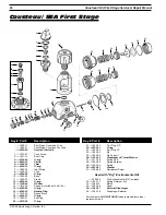
18. Using the seat extraction tool (P/N 1094-36), press the
crown(11) out of the first stage body by inserting the pin
through the low pressure side (see Fig. 3). Carefully pull the
crown out of the body, being careful to prevent damage to the
sealing surfaces inside the body and on the raised edge of the
crown. Remove and discard the O-ring(12).
19. Closely inspect the sealing surface inside the bore of the first
stage body to ensure that is perfectly smooth and free of any
scratches or other blemishes. If the body shows these signs of
damage or serious corrosion, it must be replaced with new
and cannot be reused.
20. Using a magnifier, closely examine the crown seating surface
to check for any signs of scratches, nicks, or other blemishes.
If found, discard the crown and do not attempt to reuse.
21. Resecure the vise mounting tool in the vise so that the first
stage is positioned standing outside the vice with either the
yoke or DIN connector facing straight up.
NOTE: Before proceeding, determine whether the first stage
is configured with a DIN or yoke connection, and refer to the
appropriate disassembly procedure provided below.
22.
Disassembly of Yoke Connection
A. Remove the yoke screw(1) and untie the dust cap(2) from
the yoke(8). Remove and discard the dust cap O-ring(3).
B. Apply a 26mm open end wrench to the inlet fitting(7).
Using firm, steady force, turn the inlet fitting counter-
clockwise to loosen and remove from the first stage body.
Lift the inlet fitting and yoke straight off the inlet boss,
and set the yoke aside.
CAUTION: It is important that the wrench is securely seated
over the entire hex surface of the inlet fitting to prevent any
damage to the part. Do not use impact to loosen.
Fig. 3


