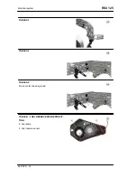
TABLE J - BATTERY AREA COMPONENTS
TABLE J1
27. Turn indicators
28. 12V 30A Fan relay
29. 30A 12V Injection relay
TABLE J2
30. Electric fan connector: insert the connector in
the specific tongue in the battery support after con-
necting it.
TABLE J3
31. 80A 12V Starter relay
RS4 125
Electrical system
ELE SYS - 81
Summary of Contents for RS4 125
Page 1: ...SERVICE STATION MANUAL B043126 RS4 125 ...
Page 5: ...INDEX OF TOPICS CHARACTERISTICS CHAR ...
Page 44: ...INDEX OF TOPICS SPECIAL TOOLS S TOOLS ...
Page 49: ...INDEX OF TOPICS MAINTENANCE MAIN ...
Page 63: ...INDEX OF TOPICS ELECTRICAL SYSTEM ELE SYS ...
Page 126: ...INDEX OF TOPICS ENGINE FROM VEHICLE ENG VE ...
Page 139: ...INDEX OF TOPICS ENGINE ENG ...
Page 146: ... Remove the oil filter Engine RS4 125 ENG 146 ...
Page 198: ...INDEX OF TOPICS POWER SUPPLY P SUPP ...
Page 203: ... Loosen the clamp and remove the throttle body RS4 125 Power supply P SUPP 203 ...
Page 204: ...INDEX OF TOPICS SUSPENSIONS SUSP ...
Page 230: ...INDEX OF TOPICS CHASSIS CHAS ...
Page 247: ...INDEX OF TOPICS BRAKING SYSTEM BRAK SYS ...
Page 262: ...INDEX OF TOPICS COOLING SYSTEM COOL SYS ...
Page 273: ...INDEX OF TOPICS BODYWORK BODYW ...
Page 290: ...INDEX OF TOPICS PRE DELIVERY PRE DE ...
Page 298: ...Windshield Wiring diagram 92 ...


