Appostar KP-5562 User Manual Download Page 5

PREFACE 

KP-5562 / KP-5564 Touch POS Terminal


iii


Important Safety Instructions 


Failure to observe these safety instructions may cause body injury, or damage to 
the product. Read these instructions carefully and keep this user manual in an 
accessible location for future reference. 


The product may cause a fire or electric shock when used 
improperly. Observe the following safety measures all the time. 

If the product is damaged, immediately turn off the power and 
disconnect the power cord. Contact your dealer for assistance. 

1.


Do not plug in or unplug the power cord with wet hands. 

2.


Do not plug the product into an AC outlet with the incorrect voltage 
(The correct voltage should be between AC 100V~240V.) 

3.


Do not plug several products in one multi-outlet. 

4.


Do not apply pressure to the power cord or place heavy objects on it. 

5.


Immediately stop using the product if it emits strange noise, odor, or smoke. 

6.


Do not use aerosol sprayers containing flammable gas inside or around the 
product. 

7.


Do not allow foreign objects or liquids to enter the product, serious damage 
may result. 

8.


Do not place the product on an unstable surface. The product may cause a 
fire if it is dropped, damaged, or broken. 

The following instructions will help you make better use of this product. 

1.


Keep the machine from locations subject to high humidity, dust, and 
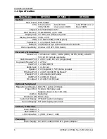
temperatures out of specification. (Refer to CH.1.4 Specification) 

2.


Clean the product by using a dry cloth or a cloth soaked with detergent. 
Never use thinner or other volatile solvent for cleaning. 

3.


At the end of the day, clean and inspect the exterior of the machine after 
turning OFF the product. 

4.


Use only specified accessories. 

5.


Do not store accessories where they might be exposed to direct sunlight, 
high temperature, high humidity, dust level, or gas. 

6.


Do not place heavy objects on top of the product /or lean against the product, 
these items may fall and cause injury. 

7.


Do not block the air vent of the product, this can cause heat to build up 
inside the box machine and may lead to fire. 


Summary of Contents for KP-5562

Page 1: ...Touch POS Terminal KP 5562 KP5564 User s Manual Edition NOVEMBER 2010 Version 1 01 http www appostar com...

Page 2: ......

Page 3: ...n outlet on a circuit different from that to which the receiver is connected Consult the dealer or an experienced radio TV technician for help Declaration of Conformity These devices comply with part...

Page 4: ...to make improvements to this publication from time to time in the contents hereof without obligation of the manufacturer to notify any person of such revision or changes Copyright This work is copyrig...

Page 5: ...se aerosol sprayers containing flammable gas inside or around the product 7 Do not allow foreign objects or liquids to enter the product serious damage may result 8 Do not place the product on an unst...

Page 6: ...Display Installation 11 2 2 Component Installation 14 2 2 1 Replacing the HDD 14 2 2 2 Compact Flash Card Installation 15 CHAPTER 3 Software Installation 17 3 1 Chipset Driver 18 3 2 Graphics Driver...

Page 7: ...ROCKPOS series is also provided with five color options on the front panel to match with the tone of the operation environments Visit our website http www appostar com or contact your system provider...

Page 8: ...rminal 1 2 Front Rear Side View Front View Dimension 390 mm W x 235 mm D x 320 mm H Rear View Dimension 390 mm W x 235 mm D x 320 mm H 15 LCD touch panel Front panel Base MSR cover Cable management co...

Page 9: ...PRODUCT OVERVIEW KP 5562 KP 5564 Touch POS Terminal 3 Side View x 2 Dimension 390 mm W x 235 mm D x 320 mm H Left Side Right Side I O with cover I O without cover...

Page 10: ...DB9 M Connector COM5 USB Serial port with RJ45 Connector x 1 See Note USB 2 0 A type Connector x 2 LAN USB RJ45 LAN Connector x 1 USB 2 0 A type Connector x 2 Keyboard Mouse PS 2 Connector Cash Drawe...

Page 11: ...municating with the server HDD LED Indicator Indicates the operational status of the Hard Disk Drive HDD The Red LED Indicator lights when HDD is being accessed Power LED Indicator Indicates the power...

Page 12: ...COM2 DB9 COM5 RJ45 all with 5V 12V DC output selectable Cash Drawer Port 1 x RJ 11 with DC 12V single dual Keyboard Mouse Port 1 x PS 2 VGA Port 1 x VGA DB15 Audio Jack 1 x Line out Speaker 2 x Integ...

Page 13: ...5568 Environment EMC Safety CE FCC Class A Operating Temperature 5 C 40 C Storage Temperature 20 C 60 C Operating Humidity 15 80 RH Storage Humidity 20 90 RH Mechanical Housing Color Cool White Dark...

Page 14: ...and the power cord is disconnected to prevent possible damage to the product 2 1 Peripheral Installation 2 1 1 Magnetic Stripe Reader MSR Installation An optional MSR can be installed in both right le...

Page 15: ...Figure 1 d ATTENTION If the MSR doesn t work properly please refer to CH 6 Troubleshooting 2 1 2 Integrated LCD VFD Customer Display Installation Step 1 Remove the customer display cover on the main u...

Page 16: ...the wafer connector to the COM 4 port with DC 5V on the mother board as shown in the picture Figure 2 d 2 e 2 f 2 g Figure 2 d Figure 2 e Figure 2 f Figure 2 g Step 4 Cover the screw holes with plasti...

Page 17: ...izontal position Figure 3 a Figure 3 a Step 2 Remove the cable management and the customer display covers on the main unit Unfasten the 2 thumb screws off both the front and rear cover of the main uni...

Page 18: ...onto the hinge Figure 3 f Make sure that the 4 connection points are connected properly Figure 3 g Figure 3 f Figure 3 g Step 5 Fit the top hinge cover and the upper hinge cover of the panel Figure 3...

Page 19: ...o the VGA port DB15 and the power cable to the 12V power output DC jack Figure 3 k Figure 3 k Step 6 Reinstall the front the rear and the cable management covers Figure 3 l 3 m Figure 3 l Figure 3 m A...

Page 20: ...ure 4 a Figure 4 a Step 2 Unfasten the 2 thumb screws off the front cover of the main unit Figure 4 b Figure 4 b Step 3 Disconnect the SATA 1 and SATA power cables from the HDD Unfasten 1 mounting thu...

Page 21: ...th the cables and then the front cover of the main unit Figure 4 e 4 f Figure 4 e Figure 4 f 2 2 2 Compact Flash Card Installation Step 1 Tilt the main LCD panel to its horizontal position Figure 5 a...

Page 22: ...emove the HDD bracket Figure 5 c 5 d Figure5 c Figure 5 d Step 4 Locate the CF card slot and insert the CF card to the slot Figure 5 e To remove the CF card push down the black lever beside the slot t...

Page 23: ...driver CD into your CD ROM drive Windows will automatically detect it and the Appostar Driver Installer appears on the screen If not locate the Setup exe file at CD and double click it to execute the...

Page 24: ...Install Chipset Driver 2 Follow the on screen instructions to complete the installation d Click Next on the Welcome screen to continue e Click Yes on the License Agreement screen to continue f Click...

Page 25: ...hics Driver 2 Follow the following instructions to complete the installation a Select English as setup language and click Next to continue b Click Next to continue c Click Install to begin the install...

Page 26: ...ll Ethernet Driver 2 Follow the on screen instructions to complete the installation a A Preparing Setup window appears Please wait b Click Next on the Welcome screen to continue c Click Install to beg...

Page 27: ...Click Install Audio Driver 2 Follow the on screen instructions to complete the installation a Click Next on the Welcome screen to continue b A progress window appears Please wait c An Installing windo...

Page 28: ...erminal 3 5 Touch Panel Driver Installation Peripheral Device Driver Installation a Click Install Peripheral Device Drivers b Click Touch Panel a Click Next on the Welcome screen b Uncheck the Install...

Page 29: ...inue d Select the None option and click Next to continue e Select the Support Multi Monitor System option Click Next to continue f Select the Destination Folder or use the default one listed g Select...

Page 30: ...n to ensure the main board is configured properly M B Layout Jumper Allocation Jumper Function Jumper Function JP1 COM1 RI function Selection JP2 Panel Mode Selection JP3 COM5 RI function Selection JP...

Page 31: ...ection JP2 Mode 1 2 short High 2 3 short Low JP3 COM5 RI function Selection JP3 Function 1 2 short 5V 3 4 short Ring In 5 6 short 12V JP4 COM5 Mode Selection JP4 Mode 1 2 3 5 4 6 short RS232 Mode 1 1...

Page 32: ...Ring In 5 6 short 12V JP9 COM4 Mode Selection JP9 Mode 1 2 3 4 short RS232 Mode 1 1 2 3 4 open RS232 Mode 2 JP10 CMOS Clear JP10 Function 1 2 Short Normal Operation 2 3 Short Clear CMOS Contents JP11...

Page 33: ...ctor allocation and its pin assignments M B Layout Connector Allocation Connector Function List Connector Function Audio1 Line out with Phone Jack Audio2 Speaker out Connector AUXFAN CPUFAN2 Fan 3Pin...

Page 34: ...r Connector PWR2 ATX Power Connector USB1 USB2 USB dual port Connectors USB3 USB4 USB port with Wafer Connectors VGA1 D sub15P CRT Connector Pin Assignment AUDIO1 Line out with Audio Phone Jack PIN No...

Page 35: ...3 27 Data 11 3 Data 4 28 Data 12 4 Data 5 29 Data 13 5 Data 6 30 Data 14 6 Data 7 31 Data 15 7 Select 0 32 Select 1 8 Ground 33 N C 9 Ground 34 IO Read 10 Ground 35 IO Write 11 Ground 36 Pull Up to 5V...

Page 36: ...RXD 4 RTS 5 TXD 6 CTS 7 DTR 8 RI 5V 12V 9 Ground 10 RI 5V 12V CPUFAN1 Fan Connector PIN No Signal Description 1 Ground 2 Fan Power 12V 3 Speed Sense 4 Control DIO1 DIO Connector with Pin Header 2 54mm...

Page 37: ...ta A3 4 Data A3 5 Clock A 6 Clock A 7 Data A2 8 Data A2 9 Data A1 10 Data A1 11 Data A0 12 Data A0 13 Ground 14 Ground 15 Data B3 16 Data B3 17 Clock B 18 Clock B 19 Data B2 20 Data B2 21 Data B1 22 D...

Page 38: ...6 Data 4 19 Ground 7 Data 5 20 Ground 8 Data 6 21 Ground 9 Data 7 22 Ground 10 Acknowledge 23 Ground 11 Busy 24 Ground 12 Paper Empty 25 Ground 13 Printer Select SATA1 2 SATA Connector PIN No Signal D...

Page 39: ...Description U1 5V U5 5V U2 USBDATA0 U6 USBDATA1 U3 USBDATA0 U7 USBDATA1 U4 Ground U8 Ground L1 TXD L5 NC L2 TXD L6 RXD L3 RXD L7 NC L4 NC L8 NC USB2_COM5 USB 3 4 Connector COM5 with Dual USB RJ 45 PI...

Page 40: ...n PIN No Signal Description 1 USB 5V 2 USB 5V 3 USBDATA6 4 USBDATA7 5 USBDATA6 6 USBDATA7 7 USB Ground 8 USB Ground VGA CRT Connector with D Sub15P PIN No Signal Description PIN No Signal Description...

Page 41: ...tery ensures the settings will not be erased when the computer is turned off or reset When the computer is powered on again the system will read the settings stored in the CMOS RAM and compare them to...

Page 42: ...Temperature Fan Speed and System Voltages Value Frequency Voltage Control This setup page is to control CPU s clock and frequency ratio Load Fail Safe Defaults Fail Safe Defaults indicates the value o...

Page 43: ...two corresponding options Smart Fan Temperature and Tolerance Value in BIOS Smart Fan Temperature determines a target temperature for the corresponding fan to meet your different application needs Ho...

Page 44: ...CPU fan running at full speed under maximum temperature CPU fan running at half speed under minimum temperature NOTE By default the Smart Fan2 Temperature is preset at 50 122 Or to load the BIOS defau...

Page 45: ...problem remains unsolved contact your dealer for further assistance The Touch Panel is not working properly 1 Check whether the Touch Panel driver has been correctly installed in the PC If not reinst...

Page 46: ...ting BIOS Load optimized defaults or load SETUP Default after flashing BIOS If the system remains unstable clear CMOS to solve the problem How to clear CMOS 1 Shut down the system and switch off the p...

Page 47: ...ion with 2 screws Integrated LCD VFD Customer Display Installation Step 1 Remove the top cover on the main unit Step 2 Unfasten 2 thumb screws off the rear cover by a coin Step 3 Fix the customer disp...

Reviews: