User’s Guide – 900MHz Stereo Audio Transmitter & Receiver
5
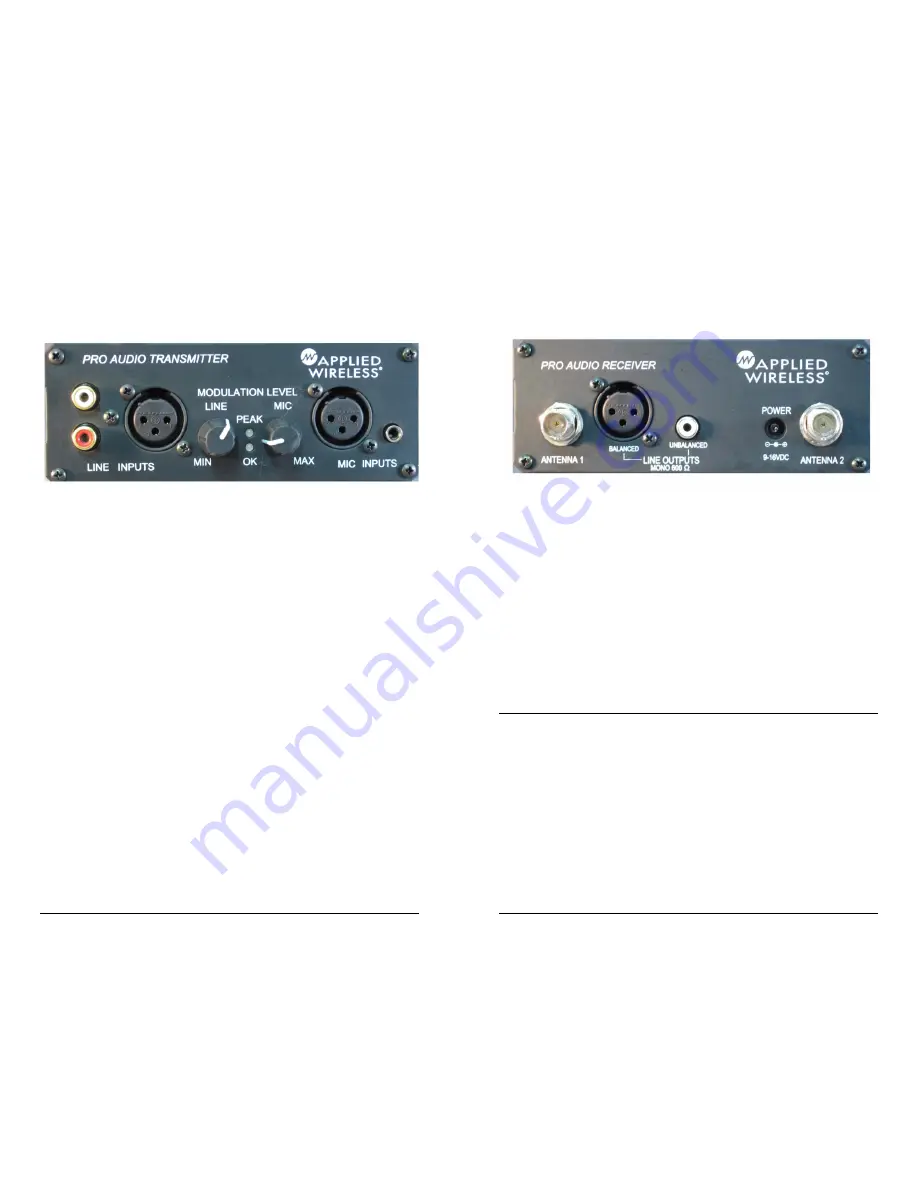
Connect a balanced or unbalanced line level audio source (outputs
from a mixer or CD player, for example) to the corresponding
XLR
OR PHONO
line-level input jacks on the transmitter’s front
panel (refer to Figure 1). Some audio devices, such as MP3
players, portable
Figure 1- Transmitter Inputs and Adjustments
CD players, and PC sound cards have a single miniature (3.5mm)
stereo phone jack (as opposed to separate RCA phono-type jacks).
To connect any of these to the transmitter, use the supplied adaptor
in conjunction with a phono cable to make the connection. Left
and right stereo inputs may be connected to the red and white
phono inputs. The output from the receiver will be monaural
however.
Mic Input
A microphone input may be used as well. Connect using either the
balanced XLR or 3.5mm connectors.
Mic Ducking Switch (rear panel)
ON: By switching the ducking switch to ON, the line input audio
will be muted when the microphone is used. When microhone
input is no longer detected, the line audio will resume.
OFF: Mic audio will be mixed with line audio.
Mic ALC Switch
ON: Prevents over-modulation distortion due to excessive mic
level.
6
Applied Wireless, Inc.
Connecting the PAR900M Receiver Audio Outputs
Connect the receivers appropriate balanced or unbalanced outputs
to the appropriate inputs on the device that is to amplify the
received audio signals (refer to Figure 2).
Figure 2- Receiver Back Panel
Connecting Power to the Transmitter and Receiver
The PAT900 and the PAR900M each require an external power
source of between 7.5 and 18 volts DC. A plug-in 120VAC-to-
9VDC power converter is supplied with each unit. Insert the power
converter’s 2.1mm plug into the
DC INPUT
jack on the unit’s rear
panel (refer to Figures 1 and 2). Plug each converter into a live
120VAC outlet. The transmitter’s red
POWER
indicator LED (on
the front panel) should illuminate. On the receiver, power on is
indicated by the illumination of the 2 digit
CHANNEL
display.
User Settings and Adjustments
Selecting the Channel of Operation (Transmitter)
Referring to Figure 3 and Table 1, select the channel on which the
transmitter will operate. Available channels are numbered 01
through 24. To select a channel, use a small flat-blade screwdriver
to rotate the selector on the
left
to the “tens digit” of the desired
channel, then rotate the selector on the
right
to the “ones digit” of
the desired channel. As an example, to select channel 16 rotate the
selector on the left to “1,” and rotate the selector on the right to
“6.” Be sure to line up the selector’s triangle-shaped pointer (
NOT
the screwdriver slot) to the desired number. Please note that setting
Figure 2 – AR900-32 Receiver (Rear Panel)


