background image

Working Standard WS 2320 

Quick Guide 


WS2320-QG44-EN


www.appliedp.com


16 

8. 

Measured Data Reading 

Step 1 

– Installation of Control Software 

It  is  necessary  to  install  to  the  PC  the  software  supplied  in  the  installation  CD  or  USB  flash  drive. 
From  supplied  medium  s

tart  the  program  “install.exe”  (when  auto-run  feature  does  not  start  it 

automatically). 

Follow the all installation steps: 

– Installation of InterBase database 

– Installation of WS Control Software 

– Database creation 

Step 2 

– Interconnection of the Device with PC 

Connect the PC to the device through the USB or RS-232 cable. 

Step 3 

– Communication Parameters Setting 

Start the program ws.exe 

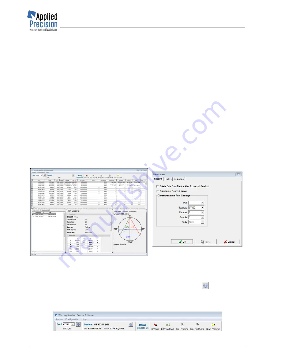
Select  menu  item 

Configuration  /  Parameters

  from  the  main  program  window  (Fig.  1)  for 

displaying communication parameters settings window (Fig. 2) 

Select correct port to which the device is connected and communication speed same as is set 
in device 


Fig. 1 - Main program window 


Fig 2 

– Communication parameters 

settings window 

Step 4 

– Measured Data Reading 

Connect  the  device  to  the  PC  and  select  the  appropriate  port  (in  the  upper  toolbar).  The  adjacent 

Device section displays ID of connected WS. You can press the refresh button  

 to re-read these 

info.  Now go to 

System / Rreadout

 from menu (or use 

Readout

 button located in top toolbar) to read 

all data from WS device.  

Measured data will be transferred into the database of the PC. 


Summary of Contents for WS 2320

Page 1: ...Working Standard Model WS 2320 Quick Guide Version 4 4 ...

Page 2: ...nd Testing Measurement is carried out in real time There are several screens available right after device is turned on The number of screens is influenced by connected probes For testing voltage current and optical sensor is needed For disk meter calibration is also required in advance Any test results can be saved in the database 1 3 How to start Situation Connection system 3P4W electronic meter ...

Page 3: ...Working Standard WS 2320 Quick Guide www appliedp com WS2320 QG44 EN 3 2 Accessories ...

Page 4: ...urrent Phase Distortion Factor of Voltage Distortion Factor of Current Active Power of Higher Harmonics f Frequency L1xx Phase Sequence L123 or L132 ΣP Sum of Active Powers ΣQ Sum of Reactive Powers ΣS Sum of Apparent Powers EP Active Energy EQ Reactive Energy ES Apparent Energy ΣEP Sum of Active Energies ΣEQ Sum of Reactive Energies ΣES Sum of Apparent Energies CT Current Transformer PT Voltage T...

Page 5: ...Working Standard WS 2320 Quick Guide www appliedp com WS2320 QG44 EN 5 4 Testing ...

Page 6: ...Working Standard WS 2320 Quick Guide WS2320 QG44 EN www appliedp com 6 5 Connection Examples 5 1 WS on Secondary Side 3P4W Basic Screens Cyclically F1 F3 from Harmonics screen ...

Page 7: ...ck Guide www appliedp com WS2320 QG44 EN 7 Cyclically button right opposite direction by left button Once button down and then right button several times Cyclically button down Other noticeable screens Meter Definition in Database ...

Page 8: ...Working Standard WS 2320 Quick Guide WS2320 QG44 EN www appliedp com 8 5 2 WS on Primary Side 1P2W Rogovski Coil Basic Screens ...

Page 9: ...Working Standard WS 2320 Quick Guide www appliedp com WS2320 QG44 EN 9 Other noticeable screens Meter Definition in Database ...

Page 10: ...Working Standard WS 2320 Quick Guide WS2320 QG44 EN www appliedp com 10 5 3 WS on Secondary Side 1P2W Basic Screens ...

Page 11: ...Working Standard WS 2320 Quick Guide www appliedp com WS2320 QG44 EN 11 Other noticeable screens Meter Definition in Database ...

Page 12: ...Working Standard WS 2320 Quick Guide WS2320 QG44 EN www appliedp com 12 5 4 Current Transformer one 3f probe no Voltage Default Screen ...

Page 13: ...Working Standard WS 2320 Quick Guide www appliedp com WS2320 QG44 EN 13 5 5 Current Transformer two 3f probes no Voltage Default Screen ...

Page 14: ...Working Standard WS 2320 Quick Guide WS2320 QG44 EN www appliedp com 14 6 Database of Meters and Test Results ...

Page 15: ...Working Standard WS 2320 Quick Guide www appliedp com WS2320 QG44 EN 15 7 Menu ...

Page 16: ...e Step 3 Communication Parameters Setting Start the program ws exe Select menu item Configuration Parameters from the main program window Fig 1 for displaying communication parameters settings window Fig 2 Select correct port to which the device is connected and communication speed same as is set in device Fig 1 Main program window Fig 2 Communication parameters settings window Step 4 Measured Dat...

Page 17: ...17 9 Optical Scanner Positioning Positioning on dynamic disc meter Cover glass Meter disc False reflection from the glass LED Detector Capturing range of the scanner Real reflection from the disc Positioning on static electronic meter Detector Cover glass Transmitter LED ...

Reviews: