background image


Chapter 8  System Monitor Utility 

TI6VGA User’s Manual 

63 

 
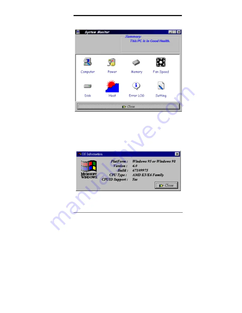
The following screen appears upon clicking on the System Monitor icon. 


Clicking on the upper left corner button would show you the latest 
company information. "Summary" provides the current system status. 
 
The section below describes the different functions of System Monitor. 
 
1.   Computer - displays the current working system version and 

processor type. 


Summary of Contents for TI6VGA

Page 1: ...TI6VGA Pentium II Apollo Pro ATX Motherboard User s Manual Version 1 0A...

Page 2: ...urer be liable for direct indirect special exemplary incidental incidental or consequential damages resulting from any defect or omission in this manual even if advised of possibility of such damages...

Page 3: ...nfiguring the Motherboard 11 4 1 CPU Frequency Setting 13 4 2 Clear CMOS Select JP6 13 4 3 JP2 7 8 SDRAM Clock Select 14 4 4 CPU Host Frequency Force Selector JP4 14 Chapter 5 Installation 15 5 1 I O...

Page 4: ...5 Chipset Features Setup 36 6 6 Power Management Setup 39 6 7 PNP PCI Configuration 42 6 8 Load BIOS Defaults 44 6 9 Load Setup Defaults 44 6 10 Integrated Peripherals 45 6 11 Supervisor User Password...

Page 5: ...scription Configuring the Motherboard Installation BIOS Configuration Audio Driver Installation Guide System Monitor Utility Checklist Please check that your package is complete and contains the items...

Page 6: ...IMM sockets or Two 168 pin DIMM sockets and 64MB SDRAM on board Memory types Extended Data Output EDO DRAM SDRAM Synchronous DRAM Memory size 8MB 16MB 32MB 64MB 128MB Chipset VIA s Apollo Pro chipset...

Page 7: ...Bus Mastering interface with DOS compatibility it supports 32 voices wavetable surround sound 3D audio and audio effects such as reverb and chorus Creative ES1373 uses single shareable PCI interrupt a...

Page 8: ...board in Figure 1 shows the location of the key components The topics covered in this chapter are as follows 3 1 Processor 6 3 2 L2 Cache 6 3 3 Main Memory 6 3 4 BIOS 8 3 5 Onboard AGP Slot 8 3 6 Winb...

Page 9: ...Chapter 3 Hardware Description TI6VGA User s Manual 5 Figure 1 Layout of the TI6VGA Motherboard Remarks The TI6VGA comes with 3 DIMM sockets or 2 DIMM sockets with 64MB SDRAM on board...

Page 10: ...t can also come with two DIMM sockets and 64MB SDRAM on board DIMM modules can be 8MB 16MB 32MB 64M and128MB in SDRAM In populating the DIMM sockets any socket can be populated first Refer to the foll...

Page 11: ...MB 64MB 64MB 32MB 96MB 128MB 32MB 160MB 32MB 32MB 8MB 72MB 64MB 32MB 8MB 104MB 128MB 32MB 8MB 168MB 32MB 32MB 16MB 80MB 64MB 32MB 16MB 112MB 128MB 32MB 16MB 176MB 32MB 32MB 32MB 96MB 64MB 32MB 32MB 12...

Page 12: ...n 3 5 Onboard AGP Slot The AGP Accelerated Graphics Port slot supports AGP compliant VGA cards to achieve rich 3D and video graphics display AGP is a platform bus specification that enables 3D graphic...

Page 13: ...Primary IDE IRQ15 Secondary IDE IRQ3 INTERRUPT IRQ4 Serial Port 1 IRQ5 INTERRUPT IRQ6 Floppy Disk Controller IRQ7 Parallel Port 1 3 9 Onboard PCI IDE The PCI IDE controller 82596 chip supports PIO mo...

Page 14: ...ller 070h 07Fh Real Time Clock NMI 080h 09Fh DMA Page Register 0A0h 0BFh Interrupt Controller 2 0C0h 0DFh DMA Controller 2 0F0h Clear Math Coprocessor Busy Signal 0F1h Reset Math Coprocessor 1F0h 1F7h...

Page 15: ...ures and proper jumper settings to configure the TI6VGA motherboard For the locations of the jumpers refer to Figure 2 4 1 CPU Frequency Setting 13 4 2 Clear CMOS Select JP6 13 4 3 JP2 7 8 SDRAM Clock...

Page 16: ...Chapter 4 Configuring the Motherboard 12 TI6VGA User s Manual Figure 2 Jumper Location on the TI6VGA Remarks The TI6VGA comes with 3 DIMM sockets or 2 DIMM sockets with 64MB SDRAM on board...

Page 17: ...CPU has been changed When this happens turn off the computer by pressing the power button and turn it on again by pressing the Insert key and the power button simultaneously Note to press the Insert k...

Page 18: ...ling to do so could lead to an unstable system JP2 7 8 Setting Function Open Run CPU Clock Short Run AGP Clock 4 4 CPU Host Frequency Force Selector JP4 The TI6VGA is able to detect the host frequency...

Page 19: ...s 17 5 2 J1 PS 2 Keyboard and PS 2 Mouse Connectors 17 5 3 J2 ATX Power Supply Connector 18 5 4 J3 Floppy Drive Connector 18 5 5 IDE1 IDE2 EIDE Connectors 19 5 6 J4 J6 Serial Ports 20 5 7 J5 Parallel...

Page 20: ...Chapter 5 Installation 16 TI6VGA User s Manual Figure 3 Connector Location on the TI6VGA Remarks The TI6VGA comes with 3 DIMM sockets or 2 DIMM sockets with 64MB SDRAM on board...

Page 21: ...to that of the connectors Refer to Figure 4 for the location and orientation of the connectors Figure 4 Orientation of the I O Connector 5 2 J1 PS 2 Keyboard and PS 2 Mouse Connectors PS 2 Mouse PS 2...

Page 22: ...Floppy Drive Connector J3 of the TI6VGA is a 34 pin header and will support up to 2 88MB floppy drives The following table shows its pin out assignments Signal Name Pin Pin Signal Name Ground 1 2 RM L...

Page 23: ...round IRQ14 31 32 No connect Address 1 33 34 No connect Address 0 35 36 Address 2 Chip select 0 37 38 Chip select 1 Activity 39 40 Ground IDE2 Secondary IDE Connector Signal Name Pin Pin Signal Name R...

Page 24: ...g indicator GND ground 5 10 Not Used 5 7 J5 Parallel Port Connector J5 is a DB 25 external connector as seen in the previous figure The following table describes the pin out assignments of this connec...

Page 25: ...5 9 J13 J14 CD ROM Audio In Connectors J13 and J14 are the onboard CD ROM audio in connectors Below are their pin assignments 4 3 2 1 1 2 3 4 J13 J14 Signal Name Pin Pin Signal Name Ground 1 1 Left L...

Page 26: ...two ports USB support allows connections of up to 64 plug and play external peripherals per channel The following table shows the pin outs of these ports Pin Signal Name 1 Vcc 2 USB 3 USB 4 Ground Po...

Page 27: ...ive LED Reset Switch Turbo LED Connector ATX Power On Switch Not Defined Power LED and Keylock Speaker Speaker Pins 1 4 This connector provides an interface to a speaker for audio tone generation An 8...

Page 28: ...is no turbo deturbo function on the motherboard The Turbo LED on the control panel will always be On when attached to this connector Pin Signal Name 8 5V 18 Ground Reset Switch Pins 9 and 19 The rese...

Page 29: ...g 33 CPU Internal Cache External Cache 33 CPU L2 Cache ECC Checking 34 Quick Power On Self Test 34 Boot Sequence 34 Swap Floppy Drive 34 Boot Up Floppy Seek 34 Boot Up NumLock Status 34 Boot Up System...

Page 30: ...ethod 40 Soft Off by PWRBTN 40 HDD Power Down 40 Doze Mode 40 Suspend Mode 40 PM Events 41 6 7 PNP PCI Configuration 42 PNP OS Installed 42 Resources Controlled by 42 Reset Configuration Data 42 IRQ3...

Page 31: ...rimary Secondary Master Slave UDMA 46 Init AGP Display First 46 Onboard FDD Controller 46 Onboard Serial Parallel Port 46 UART 2 Mode 46 IR Function Duplex 46 RXD TXD Active 46 Parallel Port Mode 46 6...

Page 32: ...r the Award BIOS is immediately activated Pressing the Del key immediately allows you to enter the Setup utility If you are a little bit late pressing the Del key POST Power On Self Test will continue...

Page 33: ...Disk Type The section below the setup items of the Main Menu displays the control keys for this menu At the bottom of the Main Menu just below the control keys section there is another section which d...

Page 34: ...ster Auto 0 0 0 0 0 0 Auto Primary Slave Auto 0 0 0 0 0 0 Auto Secondary Master Auto 0 0 0 0 0 0 Auto Secondary Slave Auto 0 0 0 0 0 0 Auto Drive A 1 44M 3 5in Base Memory 640K Drive B None Extended M...

Page 35: ...able For the Primary Master Slave as well as Secondary Master Slave you can select Auto under the TYPE and MODE fields This will enable auto detection of your IDE drives and CD ROM drive during POST P...

Page 36: ...ystem You can choose the following video display cards EGA VGA For EGA VGA SEGA SVGA or PGA monitor adapters default CGA 40 Power up in 40 column mode CGA 80 Power up in 80 column mode MONO For Hercul...

Page 37: ...on OS2 F1 Help PU PD Modify F5 Old Values Shift F2 Color F6 Load BIOS Defaults F7 Load Setup Defaults Virus Warning This item protects the boot sector and partition table of your hard disk against acc...

Page 38: ...so that Drive A becomes Drive B and Drive B becomes Drive A By default this field is set to Disabled Boot Up Floppy Seek When enabled the BIOS will seek whether or not the floppy drive installed has 4...

Page 39: ...y when the Setup utility is called up PCI VGA Palette Snoop Some non standard VGA display cards may not show colors properly This field allows you to set whether or not MPEG ISA VESA VGA Cards can wor...

Page 40: ...ctrum Disabled ESC Quit Select Item F1 Help PU PD Modify F5 Old Values Shift F2 Color F6 Load BIOS Defaults F7 Load Setup Defaults DRAM Timing The DRAM timing is controlled by the DRAM Timing Register...

Page 41: ...oard The system automatically detects the CPU bus speed 66MHz or 100MHz This field allows you to change the CPU multiplier 3X 3 5X 4X 4 5X 5X to set the correct or desired CPU frequency IMPORTANT NOTE...

Page 42: ...fault setting is 0 6 DOWN The default setting is Disabled This field is for CE Testing use only CPU Warning Temperature When the CPU reaches the CPU Warning Temperature the system alarms the user thro...

Page 43: ...Reserved Secondary PM Events IRQ12 PS 2 Mouse Primary VGA OFF IRQ13 Coprocessor Primary LPT COM LPT COM IRQ14 Hard Disk Primary HDD FDD ON IRQ15 Reserved Primary DMA master OFF ESC Quit Select Item F...

Page 44: ...ture Blank Screen This option only writes blanks to the video buffer Soft Off by PWRBTN This field defines the power off mode when using an ATX power supply The Instant Off mode allows powering off im...

Page 45: ...ce wants to gain the attention of the operating system it signals this by causing an IRQ to occur When the operating system is ready to respond to the request it interrupts itself and performs the ser...

Page 46: ...PCI ISA PnP IRQ 14 assigned to PCI ISA PnP IRQ 15 assigned to PCI ISA PnP DMA 0 assigned to PCI ISA PnP DMA 1 assigned to PCI ISA PnP ESC Quit Select Item DMA 3 assigned to PCI ISA PnP F1 Help PU PD...

Page 47: ...ys PCI data transaction By default this field is set to Enabled PCI 2 Access 1 Retry This item enables PC 2 Access 1 attempts By default this field is set to Disabled AGP Master 1 WS Write When enable...

Page 48: ...lor Load BIOS Defaults except Standard CMOS Setup To load BIOS defaults value to CMOS SRAM enter Y If not enter N 6 9 Load Setup Defaults This option allows you to load the default values to your syst...

Page 49: ...F2 Color IR Function Duplex Half F6 Load BIOS Defaults RxD TxD Active Lo Hi F7 Load Setup Defaults OnChip IDE Channel0 1 The integrated peripheral controller contains an IDE interface with support fo...

Page 50: ...field This option allows you to select the onboard FDD port Onboard Serial Parallel Port These fields allow you to select the onboard serial and parallel ports and their addresses The default values f...

Page 51: ...fter setting a password the screen automatically returns to the main screen To disable a password just press the Enter key when you are prompted to enter the password A message will confirm the passwo...

Page 52: ...Z SECTOR MODE Primary Master Select Primary Master Option N SKIP N OPTIONS TYPE SIZE CYLS HEAD PRECOMP LANDZ SECTOR MODE 1 Y 0 0 0 0 0 0 0 NORMAL NOTE Some OSes like SCO UNIX must use N N N NORMAL for...

Page 53: ...AVING ESC Quit Select Item F10 Save Exit Setup Shift F2 Change Color Save Data to CMOS Exit Setup 6 14 Exit Without Saving Select this option to exit the Setup utility without saving the changes you h...

Page 54: ...Chapter 6 BIOS Configuration 50 TI6VGA User s Manual This page was intentionally left blank...

Page 55: ...th a PCI Bus Mastering interface with DOS compatibility it supports 32 voices wavetable surround sound 3D audio and audio effects such as reverb and chorus Creative ES1373 uses single shareable PCI in...

Page 56: ...Chapter 7 Audio Driver Installation Guide 52 TI6VGA User s Manual 2 Under the Control Panel window click the System icon...

Page 57: ...Chapter 7 Audio Driver Installation Guide TI6VGA User s Manual 53 3 Click Device Manager...

Page 58: ...Chapter 7 Audio Driver Installation Guide 54 TI6VGA User s Manual 4 Click Other Device then select PCI Multimedia Audio Device and click the Remove icon...

Page 59: ...Chapter 7 Audio Driver Installation Guide TI6VGA User s Manual 55 Confirm the remove command by clicking OK...

Page 60: ...Chapter 7 Audio Driver Installation Guide 56 TI6VGA User s Manual 6 Click Close...

Page 61: ...Chapter 7 Audio Driver Installation Guide TI6VGA User s Manual 57 7 Insert the CD that comes with your motherboard into your CD ROM drive The following screen will appear Now click Sound...

Page 62: ...Chapter 7 Audio Driver Installation Guide 58 TI6VGA User s Manual 8 Click Creative Labs 1373 and then Install...

Page 63: ...ach screen until you arrive the Setup Option screen as shown below then select Full Installation 11 Proceed with Setup to install the Windows 95 98 Drivers Legacy DOS Drivers into your system 12 After...

Page 64: ...Chapter 7 Audio Driver Installation Guide 60 TI6VGA User s Manual...

Page 65: ...Chapter 7 Audio Driver Installation Guide TI6VGA User s Manual 61 This page was intentionally left blank...

Page 66: ...of systems covering areas like system temperature system voltage CPU and system fan rotational speeds If conditions become adversed that is when voltages are erratic or CPU temperature exceeds the saf...

Page 67: ...on the System Monitor icon Clicking on the upper left corner button would show you the latest company information Summary provides the current system status The section below describes the different f...

Page 68: ...Chapter 8 System Monitor Utility 64 TI6VGA User s Manual 2 Power displays the current voltage status...

Page 69: ...Chapter 8 System Monitor Utility TI6VGA User s Manual 65 3 Memory displays the current memory usage status...

Page 70: ...Chapter 8 System Monitor Utility 66 TI6VGA User s Manual 4 Fan Speed displays the current rotational speeds of CPU and Chassis fans 5 Disk displays the disk supported formats and disk space...

Page 71: ...Chapter 8 System Monitor Utility TI6VGA User s Manual 67 6 Heat displays the CPU and system temperatures 7 Error Log displays errors occuring after System Monitor is started...

Page 72: ...ge the acceptable voltage range between the MAX and MIN value Temperature temperature threshold Fan Rotation Speed the minimum rotation speed NOTE Intel has defined a margin of difference for the volt...

Page 73: ...chanism The retention mechanism that comes with your motherboard as seen in the above figure accommodates all kinds of Pentium II processors For Celeron processors place the two caps supplied on both...

Page 74: ...to it that the most up to date and accurate information are contained in this manual This section would contain page insert s of additional information updates or corrections that the user should know...

Reviews: