6
Customer Service
(704) 841-6000
www
.apolloflowcontrols.com
“Apollo”
Flow Controls
INSTALLATION, OPERATION & MAINTENANCE
MANUAL
C.
RELIEF VALVE MAINTENANCE
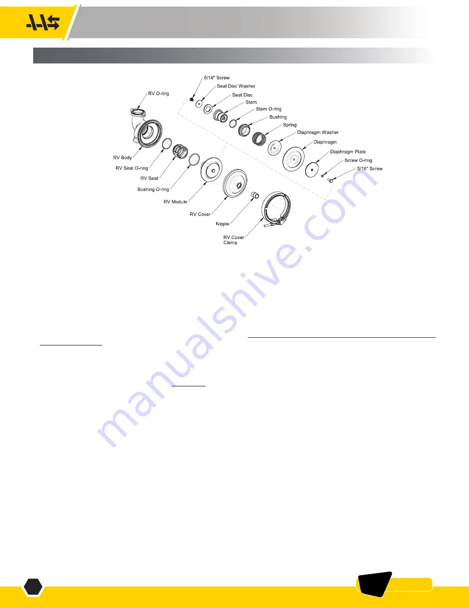
1. Unscrew the sensing hose from the nipple (sensing hose is not shown). (See Figure 5)
2. The RV can be serviced while still attached to the valve or it can be removed (rarely needed).
3. Remove the clamp by backing off the nut until the latch can be disengauged from the T-bolt. Pull the clamp apart and slide away from the RV.
4. Remove the RV cover.
5. Remove the RV module by grasping the diaphragm plate and pulling straight out.
6. Inspect the RV seat disc for debris or damage. To clean or replace the RV seat disc, remove the 5/16” screw on the seat disc washer. The RV disc
may be flipped over for a temporary repair, but should be replaced if damaged. Replace the seat disc, seat disc washer, and 5/16” screw.
7. Lubricate the bushing o-ring with Apollo® supplied lubricant, Dow 111 or equal, and insert the RV module into the valve body.
8. The RV diaphragm has a rubber bead that fits into a groove in the RV body. Ensure the diaphragm bead is seated properly in the RV body before
installing the RV cover.
If it is necessary to disassemble the RV module and/or remove the RV seat:
1. Remove the RV module as described above.
2. Remove the 5/16” screw on the diaphragm plate. Use caution as this will disengauge the spring.
3. Remove the 5/16” screw on the seat disc washer.
4. Inspect all components for damage, paying particular attention to the diaphragm, seat disc, o-rings, and stem. If any of these components are
worn or damaged, they should be replaced.
5. Lubricate the stem, stem o-ring, and RV seat o-ring with Apollo® supplied lubricant, Dow 111 or equal.
6. Reassemble RV module.
7. Remove the RV seat by grasping the cage and pulling straight out. A flat screwdriver may aid in removal.
8. Inspect the seat and seat o-ring for damage. If damaged, they should be replaced.
9. Insert the seat into the RV body. Ensure that it is fully seated.
10. Lubricate the bushing o-ring with Apollo® supplied lubricant, Dow 111 or equal and insert the assembled RV module into the valve body. Ensure the
diaphragm bead is seated properly before installing the RV cover.
11. Replace the cover and clamp.
12. Inspect the sensing hose and replace if damaged.
13. Reinstall the sensing hose to the nipple.
FIGURE 5
2-1/2” - 6” SIZES
IV.
MAINTENANCE INSTRUCTIONS - 2-1/2” – 6”


