background image

User’s Manual 


28

NOTE: You can use the domain name instead of IP address if you already set up the DNS Server 
when setting up the LAN. 


NOTE:  The e-mail address must include the “@” character to be a valid address. 
 

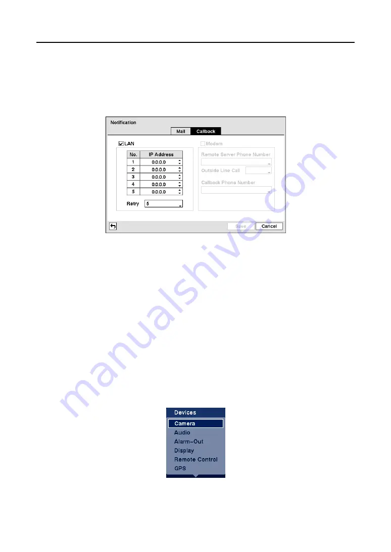
Callback 


Figure 40 

 Notification Callback setup screen 


y


LAN

:  Select to notify via LAN. 

– 

IP Address:

  Set the IP address of the computer you want contacted during an event by using the 

arrow buttons. 

– 

Retry

:  Choose the number of times you would like the DVR to try contacting the computer from 

the drop-down list. 

y


Modem

: Select to notify via modem. 

– 

Remote Server Phone Number

:  Enter the telephone number of the computer running RAS. 

– 

Outside Line Call

:  Enter any numbers that must be dialed for an outside line for your telephone 

system; for example, “9”. 

– 

Callback Phone Number

:  Enter the telephone number of the DVR. 


Configuring Devices 

 
You can configure the video, audio, alarm, display, remote control and GPS devices connected to the 
DVR. 


Figure 41 

 Devices Menu. 


Summary of Contents for RoadRunner MR2B Series

Page 1: ......

Page 2: ......

Page 3: ...ROVIDE REASONABLE PROTECTION AGAINST HARMFUL INTERFERENCE WHEN THE EQUIPMENT IS OPERATED IN A COMMERCIAL ENVIRONMENT THIS EQUIPMENT GENERATES USES AND CAN RADIATE RADIO FREQUENCY ENERGY AND IF NOT INS...

Page 4: ...If the equipment does not operate normally by following the operating instructions adjust only those controls that are covered by the operating instructions as an improper adjustment of other control...

Page 5: ...S232C Port 6 Network Port 7 Power In 7 Rear Panel Cover 7 DCP Installation 8 Installing the Standard DCP 8 Installing the Premium DCP 9 Chapter 3 Configuration 11 Front Panel Controls 11 Standard DCP...

Page 6: ...Mode 54 Freeze Mode 55 Zoom Mode 55 PTZ Mode 55 GPS Information 56 Event Monitoring 56 Covert Camera 56 Recording Video 57 Recording Audio 57 Playing Recorded Video 57 Searching Video 58 Go to the Dat...

Page 7: ...th USB Interface 69 Appendix F Connector Pin Outs 70 I O Connector Pin Outs 70 RS485 Connector Pin Outs 70 Appendix G Troubleshooting 70 Appendix H Map of Screens 71 Appendix I System Log Notices 72 A...

Page 8: ...igure 24 Device Format screen 19 Figure 25 Device Information screen 19 Figure 26 Storage Status screen 20 Figure 27 User setup screen 20 Figure 28 New Group setup screen 21 Figure 29 New User setup s...

Page 9: ...Loss Settings screen 43 Figure 73 Video Loss Actions 1 screen 44 Figure 74 Video Loss Actions 2 screen 45 Figure 75 Text In Settings screen 45 Figure 76 Text In Device Settings screen 46 Figure 77 Te...

Page 10: ...User s Manual viii...

Page 11: ...uring Playback y User friendly Graphical User Interface GUI Menu System y Multiple Recording Modes Time lapse Pre event Alarm Motion and Panic y 2 Channel Audio Recording and 1 Channel Audio Playback...

Page 12: ...ly by connecting via Ethernet There are two USB ports that can be used to upgrade the system or copy video clips to external hard disk CD RW and flash drives NOTE This manual covers the 4 and 8 channe...

Page 13: ...N HOLES IF YOU ARE INSTALLING THE DVR IN AN ENCLOSED AREA MAKE CERTAIN THERE IS ADEQUATE VENTILATION CAUTION The DVR must be mounted level using the floor bracket to attach it to the floor or the ceil...

Page 14: ...al cables from the video sources to the BNC Video In connectors Audio In Out NOTE It is the user s responsibility to determine if local laws and regulations permit recording audio NOTE The DVR does no...

Page 15: ...successfully resets to factory defaults its live video will begin showing on the monitor 5 Release the reset switch All of the DVR s settings are now at the original settings it had when it left the...

Page 16: ...al signal to the Alarm Reset In can be used to reset the Alarm Out signal Mechanical or electrical switches can be wired to the ARI Alarm Reset In and G Ground connectors The threshold voltage is belo...

Page 17: ...lthough it is possible to connect only one of the two pins it is recommended to use two wires to create a more stable current path CAUTION Even if you do not plan to use the delayed shut off feature i...

Page 18: ...IVER S VIEW OR REACH FAILING TO HEED THESE WARNINGS COULD CAUSE AN ACCIDENT CAUSING SERIOUS INJURY OR DEATH Installing the Standard DCP Figure 5 Standard DCP Installation Connecting the DB 9 Connector...

Page 19: ...DC power strip as shown below Red wire 12VDC Out Black wire Ground G Connecting the Monitor and Amplifier You can connect a monitor and amplifier to the DCP y When connecting a monitor to the DCP conn...

Page 20: ...NITOR CONNECTED TO THE DVR DURING NORMAL VEHICLE OPERATION IT IS EXTREMELY IMPORTANT THAT THE MONITOR AMPLIFIER AND CABLES DO NOT INTERFERE WITH ANY OF THE VEHICLE S CONTROLS IT IS ALSO IMPORTANT THAT...

Page 21: ...sually less than 6 feet Use the USB cable provided with the hard disk drive to connect it to the DVR Removable HDD The hard disk drive can be removed to view the video on the personal computer or on a...

Page 22: ...de in the multi screen format and displays the clip copy screen in the full screen format It displays the PTZ menu in the PTZ mode It closes the current menu or setup dialog box y PAUSE PLAY ENTER but...

Page 23: ...in 6 seconds after the shutdown message appears Initial Unit Setup Before using your DVR for the first time you will want to establish the initial settings This includes items such as time and date di...

Page 24: ...rongly recommended Setup Screen When you log in to the DVR the following setup screen appears on the screen Select the desired menu Figure 13 Setup screen Selecting Setup Menu enters the setup screen...

Page 25: ...r DVRs through the RS485 port NOTE You cannot use the same ID number for two or more DVRs that are in the same RS485 network It is possible to have multiple DVRs with System ID 0 that are in the same...

Page 26: ...e file Available upgrade package file names are listed in the drop down list The rui indicates that the file is for software upgrades and ofi indicates that the file is for optical drive firmware upgr...

Page 27: ...re 20 Date Time setup screen y Date Set the date of the system Select the individual sections of the box and adjust numbers by using the arrow buttons Selecting Format allows you to choose the date fo...

Page 28: ...ou can set up time synchronization between the DVR and standard time servers that are available in most time zones and countries or between the DVR and another DVR Figure 22 Time Sync screen y Automat...

Page 29: ...n be saved on a CD RW or DVD RW Select the box to change the setting Figure 24 Device Format screen NOTE The DVR does NOT support USB hard disk drives with a version lower than 2 0 NOTE System upgrade...

Page 30: ...ge device N A Storage conditions are normal however the S M A R T monitoring is not working or supported NOTE When the storage condition is Bad the Event Status Storage screen displays and you can che...

Page 31: ...ser out of the system first and then delete the user y Group Add a group and enter the group name using a virtual keyboard Then the New Group screen appears The authority levels that can be turned On...

Page 32: ...a user y Auto Logout Choose the time that the user will be automatically logged out Shutdown Select Shutdown in the System menu and the Shutdown screen appears asking you to confirm whether or not yo...

Page 33: ...Speed Set the transfer speed by using the arrow buttons and select the unit of measure for the transfer speed between bps and ips y Quality Choose the quality for transferred image NOTE The higher Qua...

Page 34: ...nnection by using a virtual keyboard Selecting Save reads the current IP address of the DVR NOTE ADSL and modem cannot be configured at the same time If the DVR is configured by modem the ADSL with PP...

Page 35: ...running RAS CAUTION When changing the port settings you must change the port settings on the PC running RAS as well Refer to the RAS manual for details Modem Figure 36 Modem setup screen NOTE If the...

Page 36: ...trator NOTE You can use the domain name instead of IP address if you already set up the DNS Server when setting up the LAN y Port Set the port number of the DVRNS server by using the arrow buttons y U...

Page 37: ...on in the Network menu and the Notification screen appears Mail Figure 38 Notification Mail setup screen y Enable Select if Mail is enabled y SMTP Server Enter the IP address or domain name of the SMT...

Page 38: ...y using the arrow buttons Retry Choose the number of times you would like the DVR to try contacting the computer from the drop down list y Modem Select to notify via modem Remote Server Phone Number E...

Page 39: ...n selecting the Covert 1 the DVR displays the camera title and status icons on the covert video When selecting the Covert 2 the DVR displays only camera title on the covert video NOTE A user who does...

Page 40: ...d up to two audio inputs Choose cameras that you want to associate with that audio input You cannot associate the same camera with two audio inputs y Enable Audio Out Select to enable audio out NOTE T...

Page 41: ...he alarm output for NO or NC normally open or normally closed y Dwell Time Set the dwell time of the alarm output Schedule Figure 48 Alarm Out Schedule screen y Add an alarm outputs schedule y Day Cho...

Page 42: ...The number of screen group displays when the DVR is not in the 3x3 mode 2x2 for 4 channel DVR Free Space The icon displays when the DVR is in the Recycle mode and the percentage of available storage s...

Page 43: ...he different screen layouts pages so that all the cameras will be displayed You can also set up the DVR to display one camera or a group of cameras all the time while cycling through the remaining cam...

Page 44: ...Data Bits and Stop Bits NOTE The remote keyboard cannot be configured if the RS232 port and RS485 port are in use for PTZ control networking text input or GPS y Remote Control Product Select the devi...

Page 45: ...it located on the screen Recording Settings Your DVR offers a variety of flexible recording modes You can set it up to record all the time or to only record events It can be set up to continue recordi...

Page 46: ...ding Schedule Setup Select Schedule in the Record menu and the Schedule setup screen appears Figure 56 Schedule setup screen You can program the DVR to record only during certain times based on time d...

Page 47: ...tails y Delete the recording settings You will be asked to confirm that you want to delete the settings y Default Select to set the default value and the Default screen appears Pre Event Setup Select...

Page 48: ...ch alarm y No Select to set alarm in events for entire alarm in devices No or an individual device y Title Enter the Title of each input by using the virtual keyboard y Type Set each input as NO norma...

Page 49: ...Out connectors NOTE For the Record action the camera you select should be set to the Event or Time Event recording mode in the Record Schedule setup screen NOTE For the Alarm Out action the alarm outp...

Page 50: ...menu and the Motion Detection setup screen appears Settings Figure 64 Motion Detection Settings screen y No Select to set the video motion detection for entire cameras No or an individual camera y Se...

Page 51: ...on ignoring dwell intervals NOTE The record action for motion events will not be affected by the Motion Ignoring function y Daytime Setup Select to display the Daytime Setup screen The Motion Detectio...

Page 52: ...ed Alarm Out connectors NOTE For the Record action the camera you select should be set to the Event or Time Event recording mode in the Record Schedule setup screen NOTE For the Alarm Out action the a...

Page 53: ...he DVR detects motion on the selected camera s input Video Loss Setup Select Video Loss in the Event menu and the Video Loss setup screen appears Settings Figure 72 Video Loss Settings screen The DVR...

Page 54: ...Record action the camera you select should be set to the Event or Time Event recording mode in the Record Schedule setup screen NOTE For the Alarm Out action the alarm output you select should be set...

Page 55: ...Figure 75 Text In Settings screen The DVR can be set to react to text input from devices such as ATMs Automated Teller Machines and POS Point of Sale i e cash registers This screen allows you to confi...

Page 56: ...elect Any Character if you want the DVR to react to any character sent from the text input device NOTE If Any Character is selected you will not be able to enter any text in the Transaction Start box...

Page 57: ...the Record action the camera you select should be set to the Event or Time Event recording mode in the Record Schedule setup screen NOTE For the Alarm Out action the alarm output you select should be...

Page 58: ...the Event menu and the System Event setup screen appears Health Check Figure 79 Health Check screen The DVR can be configured to run self diagnostics and report the results y System Choose the interva...

Page 59: ...Disk Almost Full Notify Choose the percentage level of disk usage at which you want the DVR to trigger an alert y Disk S M A R T Select Setup to run S M A R T and the S M A R T Setup screen appears F...

Page 60: ...M A R T check Actions Figure 83 System Event Actions screen The DVR can be set to react to system events System events can be associated with an Alarm Out connector and or notify a number of different...

Page 61: ...up screen on the Event menu y Check Alarm In and Check Recording The camera number or the box is highlighted when each event is detected based on the settings you made in the System Event setup screen...

Page 62: ...User s Manual 52...

Page 63: ...unit will turn off and will turn on again when the temperature rises above 0 Live Monitoring As soon as the DVR completes its initialization process it will begin showing live video on the attached mo...

Page 64: ...or are set to Covert unless the user has authority to view covert cameras that page will be excluded from the sequence NOTE The Full Sequence for the full sequence monitoring and the Cameo Sequence fo...

Page 65: ...screen if the PTZ camera are installed and set up properly in the Camera setup screen PTZ tab Selecting PTZ in the Live Monitoring menu displays the PTZ camera menu Select the PTZ camera you wish to c...

Page 66: ...displays the selected camera or returns to the previous screen format Covert Camera If a camera is set up as Covert 1 in the Camera setup screen Settings tab that camera will not be displayed unless a...

Page 67: ...l not operate Although you will be able to record without changing the unit from its original factory settings you will want to take advantages of the DVR s many tools See Chapter 3 Configuration for...

Page 68: ...he last recorded image y Go to the Date Time Searches by date and time see below for more details y Calendar Search Searches using a calendar see below for more details y Event Log Search Selects vide...

Page 69: ...rded video NOTE It is possible that no recorded image displays on the current screen Click the left mouse button on the screen to change the screen mode to 3x3 2x2 for 4 channel DVR You will be able t...

Page 70: ...that you want to search for any reports of event recorded data The DVR will display the events not the camera channels that occurred and that also are recorded on the camera channel that you selected...

Page 71: ...itions y Name Enter the text to search by using the virtual keyboard y Comp Enter the comparison operator by using the virtual keyboard y Value Enter the comparison value by using the virtual keyboard...

Page 72: ...in Blocks will only be available if Motion Search is selected Figure 99 Motion Search Option screen When you search for motion events of another camera you will be asked whether or not you want to del...

Page 73: ...will ask if you want to copy as much of the video clip as possible in the available space Select Continue to continue clip copy Once the clip copy starts you can cancel it by selecting Cancel or hide...

Page 74: ...User s Manual 64...

Page 75: ...rchase of the power conditioner NOTE Use the enclosed screws to make the power conditioner immovable and install it closely enough to the DVR for the cables to reach the connectors NOTE The power cond...

Page 76: ...ve in Windows 98 NOTE Preparing a USB IDE hard disk drive under Windows ME is almost identical to Windows 98 1 Connect the USB IDE hard disk drive to your computer using the USB Cable 2 Turn on your c...

Page 77: ...95 1 s 1 95 total 16 85 Thank you In the above text in data you can find that the comparison value is located at 17th Unit price mark will be ignored automatically 28th Qty and 40th amount characters...

Page 78: ...mparison value is located at 17th Unit price mark will be ignored automatically 28th Qty and 40th amount characters including spaces from the left but the value of amount category is located on a diff...

Page 79: ...rom four to five o clock during the overlapping time range using a search menu such as Event Log Search Text In Search or Motion Search it is possible for the DVR to have two overlapping start and sto...

Page 80: ...ooting Problem Possible Solution No Power Check power connections No Live Video y Check camera video cable and connections y Check monitor video cable and connections y Confirm that the camera has pow...

Page 81: ...Mobile Digital Video Recorder 71 Appendix H Map of Screens...

Page 82: ...2 Mounting failed 3 Software version error 3 No media 4 Kernel version error 4 Invalid media 100 Upgrade device mounting failed 5 File already existed 101 Package is not found 6 Not enough space 102...

Page 83: ...NC Input 2 Line In Audio Output BNC Output 1 Line Out Text Input POS Interface ATM Interface GPS Input GPS Interface CONNECTORS Video Input Composite 4 or 8 BNC Monitor Output Composite 1 BNC Audio In...

Page 84: ...or human health from uncontrolled waste disposal please separate this from other types of wastes and recycle it responsibly to promote the sustainable reuse of material resources Household users shou...

Reviews: