background image


Testing installation 

If the unit has a default configuration  
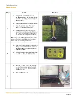
1.  Connect the power on. 
2.  Status led is red when the software is started (this takes about 30s). 
3.  Status led is green when GPS fix is received (this takes about another 30s). Now the unit is working correctly. 

If the unit has a service providers configuration follow their instruction, for example ensure that data is sended to the server. 


NOTE!

 This connection guide contains only example connections, not exact application specific connection


Summary of Contents for A9 PRO

Page 1: ...ts following devices D108300 A9 PRO Order code K521000 Important Please read this installation guide before the installation Aplicom Oy P O Box 33 FI 44101 Äänekoski Finland Telephone 358 10 841 9414 Business ID 0995791 7 Äänekoski Info aplicom fi www aplicom com ...

Page 2: ...tart the unit immediately for full operation 1 Open the unit 2 Install SIM card 3 Close the unit 4 Connect external power cabling and other needed connections 5 Mechanically install the unit to carefully selected place 6 Connect the vehicle power supply to A9 wiring power supply with fuse protection Insert the SIM card by opening the A9 PRO unit Press locking lid on the other end of the device and...

Page 3: ...ation to places of direct sunlight and extreme temperature Note that unit includes internal GPRS and shouldn t be installed in metal cage Unit s product label is installed under top cover Note Install the A9 PRO unit as far away as possible minimum 1 metres recommended from the car radio and its antenna or other electrical devices to avoid any interference ...

Page 4: ...surface on which the unit shall be fixed Use the fastener which is delivered in the package Figure 7 There are three mounting lugs on the sides of the A9 PRO device cover Install the A9 PRO device using these mounting lugs with the cable tie A Put the cable tie through the openings There is also an optional cable tie opening B which can be used Maximum width of the cable tie is 4 8mm B A ...

Page 5: ...t to a place where unit s internal antenna have the best possible visibility to GSM GPRS network base stations External GPS antenna Install the GPS GLONASS antenna to a place where it has the best possible open sky view Please note that Aplicom supplied antennas are installed inside the vehicle on dashboard on any surface or windshield depending on selected antenna type The antennas direction to s...

Page 6: ...6 Notice that the cable angle shouldn t be too tight Figure 8 Figure 9 Figure 10 Connector sticker ...

Page 7: ...ANH Pin 7 CANL Pin 8 DIN3 AD3 Pulse3 Pin 9 GPIO Black Red Green Violet Blue Yellow Grey Orange White 1 wire cable Pin 1 1 Wire PWR Pin 2 1 Wire Data Pin 3 GND SW CFG Pin 1 A9 TxD Pin 2 A9 RxD Pin 3 GND Used to SW configuration COM1 port sw option and SW debug Note Use only Aplicom specific cable Figure 11 Figure 12 Figure 13 ...

Page 8: ...bout 30s 3 Status led is green when GPS fix is received this takes about another 30s Now the unit is working correctly If the unit has a service providers configuration follow their instruction for example ensure that data is sended to the server NOTE This connection guide contains only example connections not exact application specific connection ...

Page 9: ...9 Figure 14 Connection guide Note If DIN1 is in IGN use then DIN2 DIN3 and GPIO are usable inputs iButton 3PAD POTENTIOMETER ...

Page 10: ...lled CE marking Approvals according to directives 2011 65 EU RoHS 2014 53 EU RED ECE r 10 05 E type approval Common connections Internal GSM antenna MCX for GPS antenna 1 x Molex Microfit 9 pin for PWR and IO 1 x Molex Microfit 3 pin for 1 Wire interface Relative humidity 95 max Note 1 Ensure SIM cards operating temperature range from telecom service provider WARNINGS Warranty is voided if case is...

Page 11: ...cable connector from A9 during the transport Disconnecting the cable disconnect the A9 internal battery from the A9 internal electronics for safety If A9 PRO A is used install external communication antenna minimum 1 metres from the device itself Battery safety instruction CAUTION Failure to observe the safety instructions can result in fire electric shock and other injuries or damage to the devic...

Page 12: ... device Check that vehicle windows do not have heating system that may block the GPS GLONASS signals for example in dashboard or windshield installations Check the antenna right orientation towards the GPS satellites and correct fixing place and surface POWER ON DEVICE Connect PWR and if IGN is used turn it on If movement wake up is used cause movement to start up the unit FINAL CHECK Before compl...

Page 13: ... Therefore we reserve the right to make changes and improvements to any of the products described in this guide without prior notice Due to these improvements the contents of this manual are subject to change without notice Aplicom Oy is not responsible for any loss of data income or any consequential damage This crossed out wheelie bin means that within the European Union the product must be take...

Reviews: