APLICOM A1 Installation Manual Download Page 6


5

WARNINGS 
 

  Warranty void if case is damaged. 

  A1  device  and  all  peripherals  must  be  powerless  during  the  installation.  Turn  off  ignition  and 

disconnect power. 

  Do not use detergents to clean the device. 

  GPRS may interfere sensitive electronics. 

  All devices connected to A1 device must have a fuse protection. 

  Power, ignition and signal wires connected to A1 must be fuse protected, max 10A. 

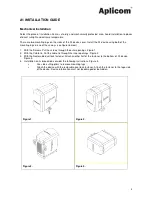
  It is recommended to use installation materials provided Installation Kit for A1 for installation. 

  As a rule, when pulling Aplicom cables through inlets or tubes during installation, it is not allowed to 

pull directly from connectors. Instead the pull must be directed to cable itself.  
For example, in cable D335083 there's heat shrink assembled just next to Microfit connector (A1 end 
on the cable), which can be utilized for pulling. 

  Connector bodies of the antennas are conical. Avoid extreme torque. 

  The place of installation should be safe from detergents and corrosive substances. 

  Do not install unit in places were safety maybe compromised. 

  PWR connector Pin 3, +12V, Ext. Battery is only for 12 volt lead acid battery do not use it with any 

other power sources.


  Ensure CAN connection and limitations from vehicle manufacturer or dealer.


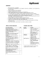
INSTALLATION CHECKLIST 
 

Action/Functionality 

OK 

DEVICE INSTALLATION 
The place of installation is safe from 
accidental knocks and excessive humidity. 


Unit identification label is protected. 


Device is fastened tightly. 


CABLES 
The cables are led carefully along a well-
protected route to the device and the 
peripherals. 


All cables are correctly connected and 
secured with fuses. 


The cables are fastened or supported in 
such a way that during use they exert no 
torsion on the connectors. 


ANTENNAS 
GSM antenna is fitted in such a way that its 
visibility to base stations is as unobstructed 
as possible (vehicle roof; as far as possible 
away from other antennas, flashing lights 
etc.). 


GPS antenna is fitted in such a way that its 
satellite visibility is as unobstructed as 
possible (vehicle roof; as far as possible 
away from other antennas, flashing lights 
etc.). 


Antenna cables are led carefully along a 
well-protected route to the device.


POWER ON DEVICE


Connect PWR and turn IGN on. 


Check that power indication LED A is 
green. 


TROUBLE SHOOTING  
 

Problem 

Solution 

No power. 

Check that all cables and 
fuses are connected.  
PWR is connected and IGN 
is on. 
Power indication LED A is 
green after power is 
connected and IGN is on. 

No GPRS 
connection. 

Check that SIM card is 
inserted.  
Check PIN CODE 
requirements from 
application manual. 

No GPS position.  

Check that the GPS antenna 
has open sky view. 
Check interferences from 
other structures to GPS 
antenna. 
NOTE! Electronic heated 
windshield may disturb GPS 
antenna sky view. 


If none of the above helps, please contact your 
equipment dealer for further assistance.


Summary of Contents for A1

Page 1: ...der code K503001 Important Please read this installation guide before the installation Aplicom Oy P O Box 33 FI 44101 Äänekoski Finland Telephone 358 14 529 011 Fax 358 14 529 0190 Business ID 0995791 7 Äänekoski Info aplicom fi www aplicom com ...

Page 2: ...Therefore we reserve the right to make changes and improvements to any of the products described in this guide without prior notice Due to these improvements the contents of this manual are subject to change without notice Aplicom Oy is not responsible for any loss of data income or any consequential damage This crossed out wheelie bin means that within the European Union the product must be taken...

Page 3: ...e Screws Put the screws through the outer openings Figure 1 2 With the Cable tie Put the cable tie through the inner openings Figure 2 3 With the Reclosable dual lock fastener Attach another half of the fastener to the bottom of A1 device Figure 3 4 Installation on its broadside consider the following instructions Figure 4 Use side cutting pliers to remove mounting lugs Attach the device with the ...

Page 4: ...us terminator resistor 120Ω The led beside the battery connector indicates the battery charging state When lit Green battery is fully charged Yellow charging is in progress Red indicates an error condition e g battery overheating Disconnecting ground lines shall not be done while unit is connected to power supply of the vehicle This will cause voltage leak between IO connections causing possible p...

Page 5: ...nal battery option 260g GPS antenna power supply 3Vdc Housing material IP31 IP54 option Plastic ABS PC PC TPE SEBS Fuse External fuse on power cable D335001 3A Max 10A Internal fuse 3A slow User interface SIM card slot Indicators LEDs Led A Power on Led B JAVA appl Led C JAVA appl Led D JAVA appl Reset switch Led internal battery charger Operating temperature 30 C 60 C see Note 1 5 C 60 C With int...

Page 6: ...nstallation is safe from accidental knocks and excessive humidity Unit identification label is protected Device is fastened tightly CABLES The cables are led carefully along a well protected route to the device and the peripherals All cables are correctly connected and secured with fuses The cables are fastened or supported in such a way that during use they exert no torsion on the connectors ANTE...

Page 7: ...6 NOTE This connection guide contains only example connections not exact application specific connections Figure 11 Connection guide ...

Page 8: ...r maximum three years use as a predictive service action Aplicom Oy is not responsible of any loss of data income or any consequential damage and repair costs which might be caused by improper use of batteries Figure 13 A1 Power cable D335001 3m with fuse and D335007 0 5m Figure 14 Crimping the fuse holder D335001 ...

Reviews: