


4
COM 1
Pin 1, GND
Pin 2, RXD1
Pin 3, TXD1
Pin 4, DTR1
Pin 5, DSR1
Pin 6, CTS1
Pin 7, RTS1
Pin 8, RI
COM 2
Pin 1, GND
Pin 2, RXD2
Pin 3, TXD2
Pin 4, DEBUG_TX
Pin 5, DEBUG_RX
Pin 6, CTS2
Pin 7, RTS2
Pin 8, NC
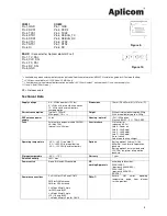
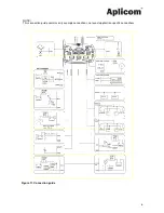
Figure 9.
DAUX
(Connector for Aplicom digital HF set)
Pin 1, TX_DAI
Pin 2, CLK_DAI
Pin 3, FS_DAI
Pin 4, RX_DAI
Pin 5, GND
Figure 10.
* = Available only when external battery option included. Additional information: K503010 Installation guide for A1 external battery
.
** = CAN bus is available in A1 FLEX and A1 MAX only
.
*** = Available only when internal battery option included. +5V, 100mA output*, active when A1 is on, same supply for
IO 1 and 2 (total 100mA max.)
NC = Not connected
Technical Data
Supply voltage
6,8…32Vdc (n12Vdc)
8…32Vdc with internal battery option
12…32Vdc with external battery
charging option
Dimensions
78mm (W) x 95mm (H) x 101mm (D)
Current consumption
Typical: < 100mA
Max (peak): 1A / < 1s
Weight
Without internal battery option: 220g
With internal battery option: 260g
GPS antenna power
supply
3Vdc
Housing / material
IP31, IP54 option
Plastic ABS+PC / PC / TPE+SEBS
Fuse
External fuse on power cable D335001:
3A (Max 10A)
Internal fuse: 3A/slow
User interface
SIM card slot
Indicators (LEDs):
Led A - Power on
Led B - JAVA appl.
Led C - JAVA appl.
Led D - JAVA appl.
Reset switch
Led internal battery charger
Operating temperature
-30
°
C...+60
°
C (see Note 1)
-5
°
C...+60
°
C With internal battery
-30
°
C...+50
°
C With external battery
Options
Battery option 1 (internal Li-Ion
800mAh), short-term full operation
back up
Battery option 2 (external lead acid
12V/7Ah), long-term full operation
back up
Storage temperature
-40
°
C...+70
°
C
Warranty
1 year
Relative humidity
+95% max
Power switch
None, IGN and SW controlled
CE
marking/Approvals
according to directives:
2004/108/EC
(previously 89/336/EEC),
2004/104/EC
(previously 95/54/EC)
99/05/EC
Common connections
2 x RJ45 for COM1 and COM2
FME for GSM antenna
SMA for GPS antenna
2 x Molex Microfit, 4 pin
for PWR and BUS1
3 x Molex Microfit, 6 pin
IO1, IO2 and BUS2,
1 x Molex Microfit 5 pin for DAUX
Note 1:
Ensure
SIM
cards
operating
temperature range from telecom
service provider.


