background image

2.2.3 Installing the Jumpers 
 

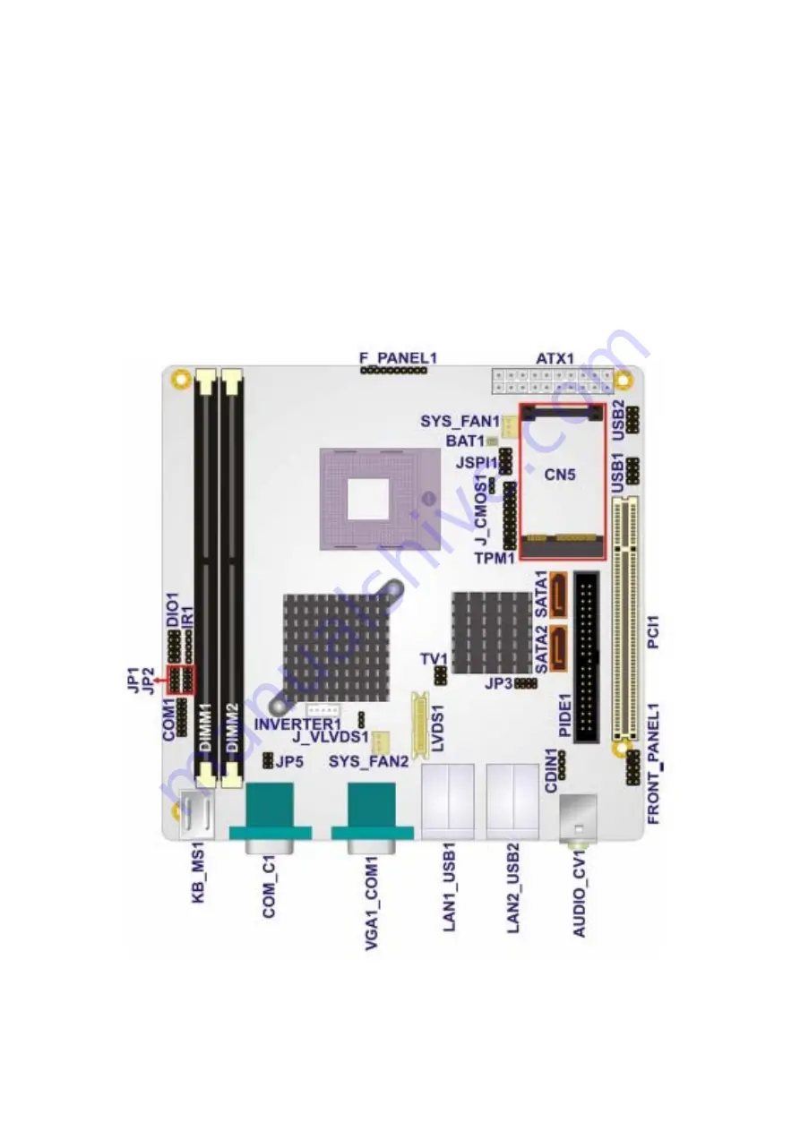
Section 2.2.3 shows peripheral interface connector locations and lists all the peripheral 

interface connectors.   

Mainboard Layout 


Figure 2.4 

shows the on-board peripheral connectors, backplane peripheral connectors and 

on-board jumpers.   


Figure 2.4: Connector and Jumper Locations 


APC-3xx7 User Manual   

18

Summary of Contents for APC-3517

Page 1: ......

Page 2: ...Nov 2008 V1 0 2008 Aplex Technology Inc All Rights Reserved Published in Taiwan Aplex Technology Inc 9F 5 No 2 Jian Pa Road Chung Ho City Taipei County Taiwan Tel 886 2 82262881 Fax 886 2 82262883 E mail aplex aplex com tw URL www aplex com tw APC 3xx7 User Manual 1 ...

Page 3: ... environment Operation of this equipment in a residential area is likely to cause interference in which case the user at his own expense will be required to take whatever measures may be required to correct the interference Electric Shock Hazard Do not operate the machine with its back cover removed There are dangerous high voltages inside Disclaimer This information in this document is subject to...

Page 4: ...ent your systems from damage Avoid your system from static electricity on all occasions Prevent electric shock Don t touch any components of this card when the card is power on Always disconnect power when the system is not in use Disconnect power when you change any hardware devices For instance when you connect a jumper or install any cards a surge of power may damage the electronic components o...

Page 5: ...4 Chapter 2 Hardware 2 1 Mainboard 15 2 2 Installations 16 2 2 1 Installing CPU 16 2 2 2 Installing Memory 17 2 2 3 Installing the Jumpers 18 2 2 4 Internal Peripheral Connectors 20 2 2 5 External Interface Connectors 35 Chapter 3 BIOS Setup 3 1 INTRODUCTION 39 3 2 MAIN 40 3 3 ADVANCED 41 3 4 PCI PNP 59 3 5 BOOT 60 3 6 SECURITY 64 3 7 CHIPSET 65 3 8 EXIT 70 Chapter 4 Installation of Drivers 4 1 In...

Page 6: ...SB Driver Installation for 5000 Boards 94 Figures Figure 1 1 APC 3517 Dimensions 7 Figure 1 2 APC 3717 Dimensions 8 Figure 1 3 APC 3917 Dimensions 9 Figure 1 4 Front View 13 Figure 1 5 Rear View 13 Figure 1 6 Panel Mounting 14 Figure 2 1 Mainboard Overview 15 Figure 2 2 Installation of CPU 16 Figure 2 3 Installation of Memory Module 17 Figure 2 4 Connector and Jumper Locations 18 Figure 5 1 Birdey...

Page 7: ...ctors 1x RS232 422 485 14 pin header Connector USB Port 4 x USB port and 4 x pin header connector Serial ATA Parts 2 x SATAII connectors with 3 0 Gbps transfer rates IDE 1 x IDE channel support 2 Ultra ATA 100 66 33 divices Extension 1 x PCI slot 1x PCIe mini card slot on board Infrared One IrDA pin header connector through the iTE IT8712F super I O Supports Serial infrared SIR Amplitude Shift Key...

Page 8: ...1 2 Dimensions Figure 1 1 Dimensions of the APC 3517 APC 3xx7 User Manual 7 ...

Page 9: ...Figure 1 2 Dimensions of the APC 3717 APC 3xx7 User Manual 8 ...

Page 10: ...Figure 1 3 Dimensions of the APC 3917 APC 3xx7 User Manual 9 ...

Page 11: ...sing or removing the chassis Step 2 Get the HDD screwed to the bracket with the four screws as shown by the arrows in the picture Step 3 Connect the cable to the HDD as shown in the picture making sure the red stripe of the cable is rightly positioned APC 3xx7 User Manual 10 ...

Page 12: ... circled tightened to secure the HDD As shown in the picture Step 5 Connect the other end of the cable to the SATA connect as shown in the picture Step 6 That s how it should look after it has been installed APC 3xx7 User Manual 11 ...

Page 13: ... the slot When the part that is interfaced together come into the right contact slightly push the addon into the rail of the slot This shows the addon is already completely connected Step 3 To finish the job just fasten the 2 screws as shown in the picture APC 3xx7 User Manual 12 After sliding the addon into the PCI expansion slot get the two screws as circled tightened to finish the connection ...

Page 14: ...300 cd m TFT LCD It is powered by an Intel Core Duo processor The industrial panel PC also features one PCI expansion slots three COM port four USB 2 0 ports one 2 5 HDD one CF slot DC power of 16 36V etc It is ideal for use as a PC based controller for Automotive Logistic Process Materials Handling and Kiosk applications Figure 1 4 Front View of APC 3xx7 Figure 1 5 Rear View of APC 3xx7 APC 3xx7 ...

Page 15: ...signed to be panel mounted and VESA mounted as shown in Picture Just carefully place the unit through the hole and tighten the given 10 screws from the rear to secure the mounting Figure 1 6 Panel mounting and VESA mounting of the APC 3xx7 APC 3xx7 User Manual 14 ...

Page 16: ...Chapter 2 Hardware 2 1 Mainboard Figure 2 1 Mainboard Overview APC 3xx7 User Manual 15 ...

Page 17: ...ecure the processor As shown in the left picture below loosen the screw first before inserting the processor Place the processor into the socket by making sure the notch on the corner of the CPU corresponds with the notch on the inside of the socket Once the processor has slide into the socket fasten the screw Refer to the figures below Figure 2 2 Installation of CPU Note Ensure that the CPU heat ...

Page 18: ...module so that the key of the DDR2 module align with those on the memory slot 2 Gently push the DDR2 module in an upright position until the clips of the slot close to hold the DDR2 module in place when the DDR2 module touches the bottom of the slot 3 To remove the DDR2 module press the clips with both hands 4 CAUTION The DIMM 1 socket must be installed with one DDR2 DIMM to enable the system to b...

Page 19: ...erface connector locations and lists all the peripheral interface connectors Mainboard Layout Figure 2 4 shows the on board peripheral connectors backplane peripheral connectors and on board jumpers Figure 2 4 Connector and Jumper Locations APC 3xx7 User Manual 18 ...

Page 20: ...ripheral Interface Connectors The Table shows a list of the peripheral interface connectors on the mainboard Detailed descriptions of these connectors can be found in this Section APC 3xx7 User Manual 19 ...

Page 21: ...This section has complete descriptions of all the internal peripheral connectors on the Mainboard Audio Connector CN Label FRONT PANEL1 CN Type 10 pin header 2x5 CN Location See Table CN Pinouts See Table The front panel audio connector connects the on board sound system of the mainboard to the audio line out and microphone jacks on the front of the computer chassis APC 3xx7 User Manual 20 ...

Page 22: ...Audio CD In Connector CN Label CDIN1 CN Type 4 pin header 1x4 CN Location See Table CN Pinouts See Table ATX Power Connector CN Label ATX1 CN Type 20 pin ATX 2x10 APC 3xx7 User Manual 21 ...

Page 23: ... The ATX connector is connected to an external ATX power supply Power is provided to the system from the power supply through this connector Fan Connectors CN Label SYS_FAN1 and SYS_FAN2 CN Type 3 pin wafer connector 1x3 APC 3xx7 User Manual 22 ...

Page 24: ...or which transfers the fan s sense signal to the system BIOS in order to recognize the fan speed Please note that only some specific types of fans offer a rotation signal Front Panel Connector CN Label F_PANEL1 CN Type 10 pin header 1x10 CN Location See Table CN Pinouts See Table The front panel connector connects to several external switches and indicators to monitor and control APC 3xx7 User Man...

Page 25: ...er HDD Digital Input Output Connector CN Label DIO1 CN Type 10 pin header 2x5 CN Location See Table CN Pinouts See Table The DIO connector is managed through a Super I O chip The DIO connector pins are user programmable The digital IO port of Mainboard is 5V CMOS level APC 3xx7 User Manual 24 ...

Page 26: ...n box header 2x20 CN Location See Table CN Pinouts See Table One primary 40 pin IDE device connector on the Mainboard motherboard supports connectivity to ATA 100 66 33 IDE devices with data transfer rates up to 100MB s APC 3xx7 User Manual 25 ...

Page 27: ...APC 3xx7 User Manual 26 ...

Page 28: ...ctor CN Label IR1 CN Type 5 pin header 1x5 CN Location See Table CN Pinouts See Table The infrared interface connector supports both Serial Infrared SIR and Amplitude Shift Key Infrared ASKIR interfaces APC 3xx7 User Manual 27 ...

Page 29: ...D Backlight Connector CN Label INVERTER1 CN Type 5 pin wafer connector 1x5 CN Location See Table CN Pinouts See Table The LCD backlight connector is for the LCD inverter connection APC 3xx7 User Manual 28 ...

Page 30: ...LVDS LCD connector CN Label LVDS1 CN Type 30 pin crimp connector 2x15 CN Location See Table CN Pinouts See Table The connector supports one or two channel 24 bit LVDS panel APC 3xx7 User Manual 29 ...

Page 31: ...nd S_ATA2 CN Type 7 pin SATA drive connectors 1x7 CN Location See Table CN Pinouts See Table The two SATA drive connectors are connected to four SATA II drives SATA II drives transfer data at speeds as high as 3 0Gbps APC 3xx7 User Manual 30 ...

Page 32: ...Serial Port Connector CN Label COM1 CN Type 14 pin header 2x7 CN Location See Table CN Pinouts See Table The serial ports connectors connect to RS 232 422 485 serial port device APC 3xx7 User Manual 31 ...

Page 33: ... Platform Module TPM Connector CN Label TPM1 CN Type 20 pin header 2x10 CN Location See Table CN Pinouts See Table The Trusted Platform Module TPM connector secures the system on bootup APC 3xx7 User Manual 32 ...

Page 34: ...in header 2x3 CN Location See Table CN Pinouts See Table The 2x3 pin TV out connector connects to a TV output by using an S Video or RCA connector The TV out connector makes displaying media data on a television easier APC 3xx7 User Manual 33 ...

Page 35: ... CN Label USB1 and USB2 CN Type 8 pin header 2x4 CN Location See Table CN Pinouts See Table One 2x4 pin connector provides connectivity to two USB 2 0 ports The USB ports are used for I O bus expansion APC 3xx7 User Manual 34 ...

Page 36: ...2 x RJ 45 Ethernet connectors 1 x Keyboard connector 1 x Mouse connector 3 x Serial port connectors 4 x USB 2 0 connectors Audio Connectors CN Label AUDIO_CV1 CN Type Audio jack CN Location See Figure 4 18 CN Pinouts See Figure 4 19 Line Out port Lime Connects a headphone or a speaker In 4 6 8 channel configuration the function of this port becomes Front Speaker Out Microphone Pink Connects a micr...

Page 37: ...r Ethernet Connectors CN Label LAN1_USB1 and LAN2_USB2 CN Type RJ 45 CN Location See Table CN Pinouts See Table The Mainboard is equipped with two built in GbE Ethernet controllers The controllers can connect to the LAN through two RJ 45 LAN connectors There are two LEDs on the connector indicating the status of LAN The pin assignments are listed in the following table APC 3xx7 User Manual 36 ...

Page 38: ...dicates activity on the port and the yellow LED indicates the port is linked Keyboard Mouse Connector CN Label KB_MS1 CN Type PS 2 connector CN Location See Figure 4 18 CN Pinouts See Table 4 22 The Mainboard keyboard and mouse connectors are standard PS 2 connectors APC 3xx7 User Manual 37 ...

Page 39: ... Table The serial ports can be connected to a serial communications device directly USB Connector CN Label LAN1_USB1 and LAN2_USB2 CN Type USB port CN Location See Figure 4 18 CN Pinouts See Table 4 24 USB devices can be connected directly to the USB connectors on the rear panel APC 3xx7 User Manual 38 ...

Page 40: ...he computer is turned on The setup program can be activated in one of two ways 1 Press the DELETE key as soon as the system is turned on or 2 Press the DELETE key when the Press Del to enter SETUP message appears on the screen If the message disappears before the DELETE key is pressed restart the computer and try again 3 1 2 Using Setup Use the arrow keys to highlight items press ENTER to select u...

Page 41: ...as the following main items Main Changes the basic system configuration Advanced Changes the advanced system settings PCIPnP Changes the advanced PCI PnP Settings Boot Changes the system boot configuration Security Sets User and Supervisor Passwords Chipset Changes the chipset settings Exit Selects exit options and loads default settings The following sections completely describe the configuration...

Page 42: ... Lists memory size The System Overview field also has two user configurable fields System Time xx xx xx Use the System Time option to set the system time Manually enter the hours minutes and seconds System Date xx xx xx Use the System Date option to set the system date Manually enter the day month and year 3 3 Advanced Use the Advanced menu BIOS Menu 2 to configure the CPU and peripheral devices t...

Page 43: ...w detailed CPU specifications and configure the CPU The CPU Configuration menu BIOS Menu 3 lists the following CPU details Manufacturer Lists the name of the CPU manufacturer Brand String Lists the brand name of the CPU being used Frequency Lists the CPU processing speed APC 3xx7 User Manual 42 ...

Page 44: ...e ATA IDE controller Disabled Disables the on board ATA IDE controller Compatible DEFAULT Configures the on board ATA IDE controller to be in compatible mode In this mode a SATA channel will replace one of the IDE channels This mode supports up to 4 storage devices Enhanced Configures the on board ATA IDE controller to be in Enhanced mode In this mode IDE channels and SATA channels are separated T...

Page 45: ...E Master Third IDE Slave Fourth IDE Master Fourth IDE Slave The IDE Configuration menu BIOS Menu 4 allows changes to the configurations for the IDE devices installed in the system If an IDE device is detected and one of the above listed four BIOS configuration options are selected the IDE configuration options shown in Section 6 3 2 1 appear 3 3 2 1 IDE Master IDE Slave Use the IDE Master and IDE ...

Page 46: ...7 GB DisabledBIOS is prevented from using the LBA mode control on the specified channel Auto DEFAULT BIOS auto detects the LBA mode control on the specified channel Block Multi Sector Transfer Auto Use the Block Multi Sector Transfer to disable or enable BIOS to auto detect if the device supports multi sector transfers Disabled BIOS is prevented from using Multi Sector Transfer on the specified ch...

Page 47: ... Ultra DMA mode 0 selected with a maximum data transfer rate of 16 6MBps UDMA1 Ultra DMA mode 1 selected with a maximum data transfer rate of 25MBps UDMA2 Ultra DMA mode 2 selected with a maximum data transfer rate of 33 3MBps UDMA3 Ultra DMA mode 3 selected with a maximum data transfer rate of 44MBps To use this mode it is required that an 80 conductor ATA cable is used UDMA4 Ultra DMA mode 4 sel...

Page 48: ...base address Disabled No base address is assigned to Serial Port 1 3F8 IRQ4 DEFAULT Serial Port 1 I O port address is 3F8 and the interrupt address is IRQ4 3E8 IRQ4 Serial Port 1 I O port address is 3E8 and the interrupt address is IRQ4 2E8 IRQ3 Serial Port 1 I O port address is 2E8 and the interrupt address is IRQ3 Serial Port1 Mode Normal Use the Serial Port1 Mode option to select the transmitti...

Page 49: ...o serial port 3 3F8 Serial port 3 I O port address is 3F8 2F8 Serial port 3 I O port address is 2F8 3E8 DEFAULT Serial port 3 I O port address is 3E8 2E8 Serial port 3 I O port address is 2E8 Serial Port3 IRQ 10 Use the Serial Port3 IRQ option to select the interrupt address for serial port 3 10 DEFAULT Serial port 3 IRQ address is 10 Serial Port4 Address 2E8 Use the Serial Port4 IRQ option to sel...

Page 50: ...ure PWM Temperature System Temperature Fan Speeds The CPU cooling fan speed is monitored Fan1 Speed Fan2 Speed Voltages The following system voltages are monitored CPU Core 1 8V 3 30V 5 00V 12 0V 1 05V 1 5V 1 25V VBAT 3 3 5 Intel AMT Configuration The Intel AMT Configuration menu BIOS Menu 8 configures the IntelR Active Management Technology AMT options APC 3xx7 User Manual 49 ...

Page 51: ... the Intel AMT support Disabled DEFAULT The IntelR AMT function is disabled Enabled The IntelR AMT function is enabled 3 3 6 Intel Robson Configuration The Intel Robson Configuration menu BIOS Menu 9 allows the IntelR Robson Technology option to be configured APC 3xx7 User Manual 50 ...

Page 52: ...onfiguration menu BIOS Menu 10 to configure remote access parameters The Remote Access Configuration is an AMIBIOS feature and allows a remote host running a terminal program to display and configure the BIOS settings Remote Access Disabled Use the Remote Access option to enable or disable access to the remote functionalities of the system Disabled DEFAULT Remote access is disabled Enabled Remote ...

Page 53: ...is made The following configuration options are available 115200 8 n 1 DEFAULT 57600 8 n 1 38400 8 n 1 19200 8 n 1 09600 8 n 1 NOTE Identical baud rate setting musts be set on the host a management computer running a terminal software and the slave Redirection After BIOS POST Always Use the Redirection After BIOS POST option to specify when console redirection should occur Disabled The console is ...

Page 54: ...PM No DEFAULT TPM support is disabled Yes TPM support is enabled Clearing the TPM Press Enter Use the Clearing the TPM option to clear the information stored in the TPM 3 3 9 USB Configuration Use the USB Configuration menu BIOS Menu 12 to read USB configuration information and configure the USB settings APC 3xx7 User Manual 53 ...

Page 55: ...ttached USB mouse or USB keyboard can control the system even when there is no USB driver loaded onto the system Disabled Legacy USB support disabled Enabled DEFAULT Legacy USB support enabled Auto Legacy USB support disabled if no USB devices are connected USB2 0 Controller Mode HiSpeed Use the USB2 0 Controller Mode option to set the speed of the USB2 0 controller FullSpeed The controller is cap...

Page 56: ...e Device field lists the USB devices that are connected to the system Emulation Type Auto Use the Emulation Type BIOS option to specify the type of emulation BIOS has to provide for the USB device NOTE Please note that the device s formatted type and the emulation type provided by the BIOS must match for a device to boot properly If both types do not match then device s behavior is undefined To ma...

Page 57: ...f 80h or above CDROM Assumes the CD ROM is formatted as bootable media All the devices that support block sizes greater than 512 bytes can only be booted using this option 3 3 10 Power Configuration Use the Power Configuration menu BIOS Menu 14 configures the Advanced Configuration and Power Interface ACPI and Power Management APM options BIOS Menu 14 Power Configuration 3 3 10 1 ACPI Configuratio...

Page 58: ...e system enters S1 POS sleep state The system appears off The CPU is stopped RAM is refreshed the system is running in a low power mode S3 STR System appears off The CPU has no power RAM is in slow refresh the power supply is in a reduced power mode 3 3 11 APM Configuration The APM Configuration menu BIOS Menu 9 allows the advanced power management options to be configured APC 3xx7 User Manual 57 ...

Page 59: ...stem turns on Last State DEFAULT The system returns to its previous state If it was on it turns itself on If it was off it remains off Resume on Ring Disabled Use the Resume on Ring BIOS option to enable activity on the RI ring in modem line to rouse the system from a suspend or standby state That is the system will be roused by an incoming call on a modem Disabled DEFAULT Wake event not generated...

Page 60: ...Enabled If selected the following appears with values that can be selected RTC Alarm Date Days RTC Alarm Time After setting the alarm the computer turns itself on from a suspend state when the alarm goes off 3 4 PCI PnP Use the PCI PnP menu BIOS Menu 17 to configure advanced PCI and PnP settings WARNING Setting wrong values for the BIOS selections in the PCIPnP BIOS menu may cause the system to ma...

Page 61: ...vailable DEFAULT The specified DMA is available to be used by PCI PnP devices Reserved The specified DMA is reserved for use by Legacy ISA devices Available DMA Channels are DM Channel 0 DM Channel 1 DM Channel 3 DM Channel 5 DM Channel 6 DM Channel 7 Reserved Memory Size Disabled Use the Reserved Memory Size BIOS option to specify the amount of memory that should be reserved for legacy ISA device...

Page 62: ...ure advanced system boot options BIOS Menu 19 Boot Settings Configuration Quick Boot Enabled Use the Quick Boot BIOS option to make the computer speed up the boot process Disabled No POST procedures are skipped Enabled DEFAULT Some POST procedures are skipped to decrease the system boot time APC 3xx7 User Manual 61 ...

Page 63: ...Number Lock key located on the upper left hand corner of the 10 key pad The Number Lock LED on the keyboard lights up when the Number Lock is engaged On DEFAULT Allows the Number Lock on the keyboard to be enabled automatically when the computer system boots up This allows the immediate use of the 10 key numeric keypad located on the right side of the keyboard To confirm this the Number Lock LED l...

Page 64: ...e Drives Use the Removable Drives menu BIOS Menu 21 to specify the boot sequence of the available USB devices When the menu is opened the USB devices connected to the system are listed as shown below 1st Drive 1st USB 2nd Drive 2nd USB APC 3xx7 User Manual 63 ...

Page 65: ...ailable devices is selected If the 1st Drive option is selected a list of available USB devices is shown Select the first USB device the system boots from If the 1st Drive is not used for booting this option may be disabled BIOS Menu 21 Removable Drives 3 6 Security Use the Security menu BIOS Menu 22 to set system and user passwords APC 3xx7 User Manual 64 ...

Page 66: ...If a user password must be installed select this field and enter the password After the password has been added Install appears next to Change User Password Clear User Password Use the Clear User Password to clear a user s password The default for this option is Not Installed If a user password must be cleared use this option 3 7 Chipset Use the Chipset menu to access the NorthBridge SouthBridge a...

Page 67: ...er ISA expansion card is used please refer to the documentation that came with the card to see if it is necessary to reserve the space Disabled DEFAULT Memory is not reserved for ISA expansion cards 15MB 16MB Between 15MB and 16MB of memory is reserved for ISA expansion cards Boots Graphics Adapter Priority IGD Use the Boots Graphics Adapter Priority option to select the graphics controller used a...

Page 68: ...e Boot Display Device option to select the display device used by the system when it boots Configuration options are listed below Auto DEFAULT CRT TV LFP Flat Panel Type 1024x768 18b Use the Flat Panel Type option to select the type of flat panel connected to the system Configuration options are listed below 640x480 18b 800x600 18b 1024x768 18b 1024x768 24b 1280x1024 48b 1600x1200 48b TV Standard ...

Page 69: ...isabled Enabled DEFAULT Southbridge HDA controller is enabled ASF Support Enabled Use the ASF Support BIOS option to control the system s ability to connect to a remote management server Disabled The system will not communicate with a remote management server Enabled DEFAULT The Alert Standard Format ASF controller is activated and can communicate with a remote management server 3 7 3 ME Subsystem...

Page 70: ...e HECI message enabled End Of Post S5 HECI Message Enabled Use the End Of Post S5 HECI Message option to enable or disable HECI message when the system is in the off S5 state Disabled The HECI message is disabled when the system is off Enabled DEFAULT The HECI message enabled when the system is off ME HECI Enabled The ME HECI option is enabled by default and can not be changed ME IDER Disabled Use...

Page 71: ...t system such as BIOS menu is displayed through the management system 3 8 Exit Use the Exit menu BIOS Menu 26 to load default BIOS values optimal failsafe values and to save configuration changes BIOS Menu 26 Exit Save Changes and Exit Use the Save Changes and Exit option to save the changes made to the BIOS options and to exit the BIOS configuration setup program Discard Changes and Exit Use the ...

Page 72: ...mal default values for each of the parameters on the Setup menus F9 key can be used for this operation Load Failsafe Defaults Use the Load Failsafe Defaults option to load failsafe default values for each of the parameters on the Setup menus F8 key can be used for this operation ...

Page 73: ...ith the motherboard The contents include Intel chipset driver VGA driver LAN drivers Audio driver iAMT Drvier Installation instructions are given below Important Note After installing your Windows operating system Windows XP you must install first the Intel Chipset Software Installation Utility before proceeding with the installation of drivers I APC 3xx7 User Manual 72 ...

Page 74: ...ipset Driver To install the Intel chipset driver please follow the steps below Step 1 Select Chipset from the list Follow the step by step installation process to install the LMS_SQL driver APC 3xx7 User Manual 73 ...

Page 75: ...APC 3xx7 User Manual 74 ...

Page 76: ...APC 3xx7 User Manual 75 ...

Page 77: ...e the Setup Complete screen appears See as picture 4 2 Intel Graphics Media Accelerator Driver To install the VGA drivers follow the steps below to proceed with the installation 1 Click Intel R GM965 Chipset Family Graphics Driver APC 3xx7 User Manual 76 ...

Page 78: ...Follow the step by step installation process to install the Graphics Media Accelerator driver APC 3xx7 User Manual 77 ...

Page 79: ...APC 3xx7 User Manual 78 ...

Page 80: ...APC 3xx7 User Manual 79 ...

Page 81: ...ver Installation Complete 4 3 Intel 82573L 82566DM LAN Device Driver To install the Intel R 82573L 82566DM Gigabit LAN connect device driver please follow the steps below Select LAN from the list APC 3xx7 User Manual 80 ...

Page 82: ...Follow the step by step installation process to install the LAN driver APC 3xx7 User Manual 81 ...

Page 83: ...APC 3xx7 User Manual 82 ...

Page 84: ...APC 3xx7 User Manual 83 ...

Page 85: ...Click FINISH A Driver Installation Complete APC 3xx7 User Manual 84 ...

Page 86: ...nstallation To install the Realtek High Definition HD Audio driver please follow the steps below Select Audio from the list Follow the step by step installation process to install the Realtek HD Audio driver APC 3xx7 User Manual 85 ...

Page 87: ...APC 3xx7 User Manual 86 ...

Page 88: ...Technology Driver Installation To install the Intel Active Management Technology IAMT driver please follow the steps below 4 6 1 Select iAMTand Utilities LMS_SQL from the list Follow the step by step installation process to install the LMS_SQL driver APC 3xx7 User Manual 87 ...

Page 89: ...APC 3xx7 User Manual 88 ...

Page 90: ...APC 3xx7 User Manual 89 ...

Page 91: ...Click Finish to complete the setup process 4 6 2 Select iAMTand Utilities HECI from the list APC 3xx7 User Manual 90 ...

Page 92: ...Follow the step by step installation process to install the LMS_SQL driver APC 3xx7 User Manual 91 ...

Page 93: ...APC 3xx7 User Manual 92 ...

Page 94: ...Click Finish to complete the setup process APC 3xx7 User Manual 93 ...

Page 95: ...ontroller that has been designed for those who may like and all in one solution with 10 bit A D converter built in to make the total printed circuit board denser circuit diagram also designed for 12 bit ADC for optional There are two connectors on this board one connector is for 4 5 8 wire touch screen cable optional and another is for 4 pin USB A type cable optional Figure 5 1 Bird s Eye View of ...

Page 96: ... 1 Please make sure your PenMount 6000 device had plugged in advance If your device uses RS232 interface please plugged in before the machine is turned on When the system first detects the controller board a screen appears that shows Unknown Device Do not use this hardware wizard Press Cancel 2 Insert the Aplex product CD install setup exe the screen below would appear Click touch panel driver APC...

Page 97: ...3 A License Agreement appears Click I accept and Next 4 Ready to Install the Program Click Install APC 3xx7 User Manual 96 ...

Page 98: ...5 Installing APC 3xx7 User Manual 97 ...

Page 99: ...6 The Install Shield Wizard Completed appears Click Finish APC 3xx7 User Manual 98 ...

Page 100: ...nt Control Panel are Device Multiple Monitors Tools and About which are explained in the following sections Device In this window you can find out that how many devices be detected on your system Calibrate This function offers two ways to calibrate your touch screen Standard Calibration adjusts most touch screens Advanced Calibration adjusts aging touch screens Standard Calibration Click this butt...

Page 101: ...tion this can uses Standard 4 9 16 or 25 points to calibrate E g Please run ms dos prompt or command prompt c Program Files PenMount Universa Driver Dmcctrl exe calibration 0 Standard Calibration Dmcctrl exe calibration 0 Standard Calibration 4 Advanced Calibration 4 9 Advanced Calibration 9 16 Advanced Calibration 16 25 Advanced Calibration 25 1 Please select a device then click Configure You can...

Page 102: ...libration points you need for an accurate calibration Use a stylus during Advanced Calibration for greater accuracy Please follow the step as below 3 Come back to PenMount Control Panel and select Tools then Click Advanced Calibration APC 3xx7 User Manual 101 ...

Page 103: ...Select Device to calibrate then you can start to do Advanced Calibration NOTE Recommend to use a stylus during Advanced Calibration for greater accuracy APC 3xx7 User Manual 102 ...

Page 104: ...Setting APC 3xx7 User Manual 103 ...

Page 105: ...About This panel displays information about the PenMount controller and driver version APC 3xx7 User Manual 104 ...

Page 106: ...e Driver installation procedures are the same as for a single monitor Multiple Monitors supports the following modes Windows Extend Monitor Function Matrox DualHead Multi Screen Function nVidia nView Function NOTE The Multiple Monitors function is for use with multiple displays only Do not use this function if you have only one touch screen display Please note once you turn on this function the Ro...

Page 107: ...GA output for multiple monitors please do not use the Multiple Monitors function Just follow the regular procedure for calibration on each of your desktop monitors 2 The Rotating function is disabled if you use the Multiple Monitors function 3 If you change the resolution of display or screen address you have to redo Map Touch Screens so the system understands where the displays are 4 If you more ...

Page 108: ...dvanced Calibration Enable Advanced Calibration function Right Button Icon Enable right button function The icon can show on Desktop or System Tray menu bar About You can see how many devices of PenMount controller that are plugged to your system APC 3xx7 User Manual 107 ...

Page 109: ...u bar of Windows 2000 XP system when you turn on PenMount Monitor in PenMount Utilities PenMount Monitor has the following function PenMount Rotating Functions The PenMount driver for Windows 2000 XP supports several display rotating software packages APC 3xx7 User Manual 108 ...

Page 110: ... Display Driver Rotate Function Intel 845G GE Display Driver Rotate Function Configuring the Rotate Function 1 Install the rotation software package 2 Choose the rotate function 0 90 180 270 in the 3rd party software The calibration screen appears automatically Touch this point and rotation is mapped NOTE The Rotate function is disabled if you use Monitor Mapping APC 3xx7 User Manual 109 ...

Reviews: