background image

WR 3M 

                    17-22 

DE 

EN 

FR


IT


ES


PT


NL


SV


DK


FI


GR


TR


CZ


PL


HU


SK


SL


EE


LV


LT


Changing calibration at 100 °C / 212 °F 
1.  Insert the temperature sensor (0.5 mm) of the external 

temperature meter into the temperature measuring tip. 

2.  Select the menu item FCC in Menu 2. 
3.  Press the DOWN button. 

Calibration point 100 °C / 212 °F is selected. 

The soldering tip is now heated to 100 °C / 212 °F.  

The control indicator flashes as soon as the temperature is 

constant. 

4.  Compare the temperatures indicated by the meter with the 

indications in the display. 

5.  Use the UP or DOWN button to set the difference between the 

value indicated on the external meter and the value indicated on 

the repair station. 

Maximum possible temperature adjustment ± 40 °C (± 72 °F).  

Example: 

Display 100 °C, external measuring instrument 98 °C:  

setting 

S

 2 

Display 100 °C, external measuring instrument 102 °C:  

setting 

T

 2  

Note  Press button ┌ 3 ┐ to exit the menu item without changes (EXIT). 

6.  Press button ┌ 2 ┐ (Set) to confirm the value. 

The temperature deviation is now reset to 0. Calibration at 

100 °C / 212 °F is now concluded. 

7.  Exit menu 2 with button ┌ 3 ┐.  
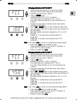
Changing calibration at 450 °C / 842 °F 
1.  Insert the temperature sensor (0.5 mm) of the external 

temperature meter into the temperature measuring tip. 

2.  Select the menu item FCC in Menu 2. 
3.  Press the UP button. 

Calibration point 450 °C / 842 °F is selected. 

The soldering tip is now heated to 450 °C / 842 °F.  

The control indicator flashes as soon as the temperature is 

constant. 

4.  Compare the temperatures indicated by the meter with the 

indications in the display. 

5.  Use the UP or DOWN button to set the difference between the 

value indicated on the external meter and the value indicated on 

the repair station. 

Maximum possible temperature adjustment ± 40 °C (± 72 °F).  

Example: 

Display 450 °C, external measuring instrument 448 °C:  

setting 

S

 2 

Display 450 °C, external measuring instrument 452 °C:  

setting 

T

 2 

Note  Press button ┌ 3 ┐ to exit the menu item without changes (EXIT). 

6.  Press button ┌ 2 ┐ (Set) to confirm the value. 

The temperature deviation is now reset to 0. Calibration at 

450 °C / 842 °F is now concluded. 

7.  Exit Menu 2 with button ┌ 3 ┐.  

PK Elektronik Vertriebs GmbH, E-Mail: [email protected], Internet: www.pkelektronik.com

Summary of Contents for WR3M

Page 1: ...EN FR IT ES PT NL SV DK FI GR TR CZ PL HU SK SL EE LV LT Weller WR 3M Reparaturstation Betriebsanleitung DE PK Elektronik Vertriebs GmbH E Mail info pkelektronik com Internet www pkelektronik com ...

Page 2: ...2 Netzschalter 13 Anschlüsse Pick Up 14 Anschluss Vakuum Vac 15 Anschluss Heißluft Air 16 Anschlussbuchsen Lötwerkzeug Kanal 1 2 3 17 Temperaturanzeige 18 Temperatursymbol 19 Zeitfunktionen 20 Verriegelung 21 Optische Regelkontrolle 22 Anzeige Kanalwahl 23 Anzeige Festtemperatur 24 Anzeige Sonderfunktionen 25 USB Schnittstelle 26 Netzsicherung 27 Netzanschluss 28 Potentialausgleichsbuchse PK Elekt...

Page 3: ...se Anleitung enthält wichtige Informationen um die Reparaturstation WR 3M sicher und sachgerecht in Betrieb zu nehmen zu bedienen zu warten und einfache Störungen selbst zu beseitigen Z Lesen Sie diese Anleitung und die beiliegenden Sicherheitshinweise vor Inbetriebnahme des Gerätes vollständig bevor Sie mit der Reparaturstation WR 3M arbeiten Z Bewahren Sie diese Anleitung so auf dass sie für all...

Page 4: ...angegebenen Zweck zum Löten und Entlöten unter den hier angegebenen Bedingungen Der bestimmungsgemäße Gebrauch der Reparaturstation WR 3M schließt auch ein dass Sie diese Anleitung beachten Sie alle weiteren Begleitunterlagen beachten Sie die nationalen Unfallverhütungsvorschriften am Einsatzort beachten Für eigenmächtig vorgenommene Veränderungen am Gerät wird vom Hersteller keine Haftung übernom...

Page 5: ...l und Ist Wert werden digital angezeigt Soll und Ist Wert werden digital angezeigt Drei Temperaturtasten dienen zur direkten Anwahl von Festtemperaturen Das Erreichen der vorgewählten Temperatur wird durch Blinken der optischen Regelkontrolle a Symbol im Display und zusätzlicher grüner LED signalisiert Die Weller WR 3M Reparaturstation bietet folgende weitere Funktionen Automatische Werkzeugerkenn...

Page 6: ...0 F WP 200 50 C 550 C 150 F 950 F WMRT WMRP 100 C 450 C 200 F 850 F DSX 80 DXV 80 50 C 450 C 150 F 850 F DSX 120 50 C 450 C 150 F 850 F HAP 200 HAP 1 50 C 550 C 150 F 950 F Temperaturgenauigkeit 9 C 17 F Temperaturstabilität 2 C 4 F Ableitwiderstand Lötspitze Tip to ground Entspricht IPC J 001 Ableitspannung Lötspitze Tip to ground Entspricht IPC J 001 Pumpe Aussetzbetrieb 30 30 s Max Unterdruck 0...

Page 7: ...streten und zu Verletzungen führen Z Schließen Sie den Vakuumschlauch nie am Air Nippel an 1 Das Gerät sorgfältig auspacken 2 Die Lötwerkzeuge wie folgt anschließen Heißluftpencil HAP mit Luftschlauch am Air Nippel 15 anschließen und mit Anschlussstecker in die Anschlussbuchse 1 2 oder 3 16 der Reparaturstation einstecken und durch kurze Rechtsdrehung verriegeln Der HAP 1 Heißluftkolben ist nur mi...

Page 8: ...wählen ein oder ausschalten 1 Eine der Tasten 1 2 oder 3 drücken um einen der drei Kanäle auszuwählen Im Display erscheinen die Soll Temperatur des angewählten Kanals sowie in kleiner Schrift die fest programmierten Temperaturen Oder Taste 1 2 3 antippen bis der gewünschte Kanal angezeigt wird Im Display erscheint dann die aktuelle Werkzeugtemperatur Im unteren Bereich wird zusätzlich der Status m...

Page 9: ...wahl von drei voreingestellten Temperaturwerten Festtemperaturen eingestellt werden Werkseitige Einstellungen 1 150 C 300 F 2 350 C 662 F 3 380 C 716 F 1 Kanal auswählen Anzeige von 3 Festtemperaturen im Display für ca 2 s Solange das Temperatursymbol blinkt kann die Temperaturwerteingabe erfolgen 2 Temperatursollwert mit Taste UP oder DOWN einstellen 3 Gewünschte Temperaturtaste 1 2 oder 3 drei S...

Page 10: ...Modus leuchtet die der Taste Pick Up benachbarte LED 8 grün Hinweis Die Vakuumpumpe ist nicht auf Dauerbetrieb ausgelegt Zum Schutz der Pumpe schaltet sich diese nach 10 Minuten Dauerbetrieb automatisch aus 6 5 Löten und Entlöten Z Führen Sie die Lötarbeiten gemäß der Bedienungsanleitung Ihres angeschlossenen Lötwerkzeuges durch 7 Sonderfunktionen Die Sonderfunktionen sind in 2 Menüebenen eingetei...

Page 11: ...en Mit Taste 3 Menü wieder verlassen EXIT Zurücksetzen der Sonderfunktionen auf die Werkseinstellungen 1 Taste 3 drücken und gedrückt halten 2 Anschließend die Tasten UP und DOWN gleichzeitig drücken Im Display erscheint FSE Die Reparaturstation ist nun wieder auf die Werkseinstellungen zurückgesetzt Standby Temperatur einstellen Nach einer Temperaturabschaltung wird automatisch die Standby Temper...

Page 12: ... auswählen 2 Setback Wert mit Taste UP oder DOWN einstellen 3 Mit Taste 1 zurück oder 2 vor zum nächsten Menüpunkt wechseln Automatische Abschaltzeit AUTO OFF einstellen Bei Nichtgebrauch des Lötwerkzeugs wird nach Ablauf der AUTO OFF Zeit die Heizung des Lötwerkzeuges abgeschaltet Die Temperaturabschaltung wird unabhängig von der eingestellten Setback Funktion ausgeführt Die Isttemperatur wird bl...

Page 13: ...r Ablage3 nach Ablauf der OFF Zeit abgeschaltet ON Time Lötwerkzeug wird in der Ablage3 auf die STANDBY Temperatur2 heruntergeregelt und nach Ablauf der OFF Zeit abgeschaltet Time 0 Lötwerkzeug wird in der Ablage3 nach der SETBACK Zeit auf die STANDBY Temperatur2 heruntergeregelt Time Time Lötwerkzeug wird in der Ablage3 nach Ablauf der SETBACK Zeit auf die STANDBY Temperatur2 heruntergeregelt und...

Page 14: ... Menüpunkt C F im Menü 1 auswählen 2 Temperatureinheit mit Taste UP oder DOWN einstellen 3 Mit Taste 1 zurück oder 2 vor zum nächsten Menüpunkt wechseln Einschaltzeit ON TIME für Heißluftkolben HAP begrenzen Die Einschaltzeit für den Heißluftstrom des HAP kann in 1er Schritten von 0 bis 60 s begrenzt werden Die eingestellte Zeit ist dann für alle 3 Kanäle gleich Werkseinstellung ist 0 s OFF d h de...

Page 15: ... Entriegelung nicht mehr verstellt werden Reparaturstation verriegeln 1 Menüpunkt LOCK im Menü 1 auswählen Im Display wird OFF angezeigt Das Schlüsselsymbol blinkt Hinweis Drücken der Tasten 1 oder 2 während OFF angezeigt wird führt zum Verlassen des Menüpunktes ohne abgespeicherten Verriegelungscode 2 3 stelligen Verriegelungscode mit Taste UP oder DOWN einstellen 3 Taste 3 5 s lang drücken Der C...

Page 16: ...llung 600 mbar Einstellbar 400 mbar bis 800 mbar 1 System Spitzen und Filter müssen frei sein 2 Menüpunkt LEVEL im Menü 2 auswählen 3 LEVEL Druckwert mit Taste UP oder DOWN einstellen Die LED Regelkontrolle schaltet von rot auf grün hin und her Mit Taste UP den Unterdruck um 50 bis 80 mbar erhöhen den Vakuumschlauch zusammendrücken und kontrollieren ob die Kontrollleuchte von grün auf rot schaltet...

Page 17: ...Beispiel Display 100 C externes Messgerät 98 C Einstellung S 2 Display 100 C externes Messgerät 102 C Einstellung T 2 Hinweis Taste 3 drücken um den Menüpunkt ohne Veränderungen zu verlassen EXIT 6 Drücken der Taste 2 Set um den Wert zu bestätigen Die Temperaturabweichung ist nun auf 0 zurückgesetzt Die Kalibrierung bei 100 C 212 F ist nun abgeschlossen 7 Mit Taste 3 das Menü 2 verlassen Kalibrier...

Page 18: ...Funktion kann der werkseitig aktivierte automatische Kanalwechsel deaktiviert werden 1 Menüpunkt AUTO CHANNEL im Menü 2 auswählen 2 Status mit Taste UP oder DOWN einstellen ON aktivieren OFF deaktivieren 3 Mit Taste 1 zurück oder 2 vor zum nächsten Menüpunkt wechseln Tastenverriegelung HAP aktivieren deaktivieren Mit dieser Funktion kann das werkseitig eingestellte Tastenverhalten des HAP Kolbens ...

Page 19: ... Filter warten Hauptfilter für VACUUM und AIR regelmäßig auf Verschmutzung kontrollieren und gegebenenfalls erneuern WARNUNG Zerstörung der Vakuumpumpe durch Arbeiten ohne Filter Z Kontrollieren Sie bevor Sie mit Lötarbeiten beginnen ob ein Hauptfilter eingelegt ist Filter austauschen 1 Abdeckkappe Vac 14 oder Air 15 um 45 nach links drehen und abnehmen 2 Verschmutzten Filter herausziehen und ordn...

Page 20: ...tauschen Federvorspannung verringern Keine Luft am HAP Luftschlauch nicht oder falsch angeschlossen Luftschlauch am AIR Nippel anschließen Kein Vakuum am Entlötwerkzeug Vakuumschlauch nicht oder falsch angeschlossen Entlötdüse verstopft Vakuumschlauch am Vac Nippel anschließen Entlötdüse mit Reinigungswerkzeug warten Statusanzeige der VAC LED s stimmt nicht Manometer Level nicht richtig eingestell...

Page 21: ...80 W T005 13 182 99DXV 80 Entlötkolbenset 80 W T005 13 183 99DSX 80 Entlötkolbenset 80 W T005 13 198 99DSX 120 Entlötkolben 120 W T005 27 118 99HAP 1 Heißluftkolbenset 100 W T005 15 154 99WRK Ablagenset T005 15 155 99WRK Entlötset T005 29 184 99 WVP Vakuumpipette T005 27 116 99HAP 200 Heißluftkolben T005 27 117 99HAP 200 Heißluftset T005 15 152 99WDH 30 Ablage für HAP 200 DSX 80 DSX 120 T005 15 15...

Page 22: ... Rückgriffsansprüche des Käufers nach 478 479 BGB Aus einer von uns abgegebenen Garantie haften wir nur wenn die Beschaffenheits oder Haltbarkeitsgarantie von uns schriftlich und unter Verwendung des Begriffs Garantie abgegeben worden ist Technische Änderungen vorbehalten Die aktualisierten Betriebsanleitungen finden Sie unter www weller tools com PK Elektronik Vertriebs GmbH E Mail info pkelektro...

Page 23: ...EN FR IT ES PT NL SV DK FI GR TR CZ PL HU SK SL EE LV LT WR 3M Operating Instructions DE PK Elektronik Vertriebs GmbH E Mail info pkelektronik com Internet www pkelektronik com ...

Page 24: ... 12 Mains power switch 13 Connections pick up 14 Connection vacuum Vac 15 Connection hot air Air 16 Connector sockets soldering tool channel 1 2 3 17 Temperature display 18 Temperature symbol 19 Time functions 20 Lock 21 Optical control check 22 Display channel selection 23 Display fixed temperature 24 Display special functions 25 USB port 26 Mains system fuse 27 Mains system connection 28 Equipot...

Page 25: ...ain important information which will help you to start up operate and service the WR 3M repair station safely and correctly as well as to eliminate simple faults malfunctions yourselves Z Read these instructions and the accompanying safety information carefully before starting up the device and starting work with the WR 3M repair station Z Ensure that these instructions are accessible to all users...

Page 26: ... Instructions namely soldering under the conditions specified here Intended use of the WR 3M repair station also includes the requirement that observing these operating instructions observing all other accompanying documentation observance of the locally applicable accident prevention regulations The manufacturer shall not be liable for damage resulting from unauthorised alterations to the machine...

Page 27: ...cted Setpoint and actual values are displayed in digital form Three temperature buttons are used to select fixed temperatures directly The optical control indicator flashes a symbol in the display and additional green LED to indicate when the preselected temperature has been reached The Weller WR 3M repair station offers the following additional functions Automatic tool detection and activation of...

Page 28: ...150 F 950 F WP 200 50 C 550 C 150 F 950 F WMRT WMRP 100 C 450 C 200 F 850 F DSX 80 DXV 80 50 C 450 C 150 F 850 F DSX 120 50 C 450 C 150 F 850 F HAP 200 HAP 1 50 C 550 C 150 F 999 F Temperature accuracy 9 C 17 F Temperature stability 2 C 4 F Soldering tip leakage resistance tip to ground Corresponds to IPC J 001 Soldering tip leakage current tip to ground Corresponds to IPC J 001 Pump periodic duty...

Page 29: ...cause injuries Z Never connect the vacuum hose to the Air nipple 1 Carefully unpack the device 2 Connect the soldering tools as follows Connect the hot air pencil HAP with air hose to Air nipple 15 and insert with the attachment plug in connection socket 1 2 or 3 16 of the repair station and lock by turning clockwise slightly The HAP 1 hot air pencil can only be connected with the air hose adapter...

Page 30: ...e display shows the setpoint temperature of the selected channel and in smaller script the permanently programmed temperatures Or Tap on the 1 2 3 button until the desired channel is displayed The current tool temperature then appears in the display The status with the corresponding setpoint temperature is also displayed in the lower area The selected channel is indicated by a triangle 21 in the d...

Page 31: ...temperature values fixed temperatures Factory settings 1 150 C 300 F 2 350 C 662 F 3 380 C 716 F 1 Select a channel 3 fixed temperatures are shown in the display for approx 2 s The temperature value can now be input as long as the temperature symbol is flashing 2 Set the setpoint temperature value with the UP or DOWN button 3 Keep the desired temperature button 1 2 or 3 pressed for 3 seconds The t...

Page 32: ...tton lights up green Note The vacuum pump is not designed for continuous operation To protect itself the pump switches off automatically after 10 minutes of continuous operation 6 5 Soldering and unsoldering Z Carry out the soldering work in accordance with the operating instructions of your connected soldering tool 7 Special functions The special functions are divided into 2 menu levels Menu 1 wi...

Page 33: ...1 2 Exit the menu again with button 3 EXIT Resetting the special functions to the factory settings 1 Press and hold down button 3 2 Then press the UP and DOWN buttons simultaneously FSE appears in the display The repair station is now reset to the factory settings Setting the standby temperature The standby temperature is automatically set after a temperature deactivation The actual temperature fl...

Page 34: ...u 1 2 Set the setback value with the UP or DOWN button 3 Proceed to the next menu item with the button 1 back or 2 forward Setting the automatic switch off time AUTO OFF When the soldering tool is not in use heating of the soldering tool is switched off after the AUTO OFF time has elapsed Temperature deactivation is performed independently of the set setback function The actual temperature flashes...

Page 35: ...off in the holder3 after the OFF time has elapsed ON Time Soldering tool is controlled down in the holder3 to the STANDBY temperature2 and is switched off after the OFF time has elapsed Time 0 Soldering tool is controlled down in the holder3 to the STANDBY temperature2 after the SETBACK time has elapsed Time Time Soldering tool is controlled down in the holder3 to the STANDBY temperature2 after th...

Page 36: ... 1 Select the menu item C F in Menu 1 2 Set the temperature unit with the UP or DOWN button 3 Proceed to the next menu item with the button 1 back or 2 forward Limiting the switch on time ON TIME for hot air pencil HAP The switch on time for the HAP hot air flow can be limited in increments of 1 from 0 to 60 s The set time is then identical for all 3 channels Factory setting is 0 s OFF i e the air...

Page 37: ...item being exited without a stored lock code 2 Set a 3 digit lock code with the UP or DOWN button 3 Press button 3 for 5 seconds The code is stored The padlock symbol is displayed The station is now locked The display switches to the main menu To unlock the repair station 1 Select the menu item LOCK in Menu 1 ON appears in the display The padlock symbol is displayed 2 Enter the 3 digit lock code w...

Page 38: ...ck or 2 forward Setting the station identification ID code When the optional USB port is used several WR 3M repair stations can be activated and remote controlled to their full operational extent To this end each station requires a station identification ID code so that it can clearly identified 1 Select the menu item REMOTE ID in Menu 2 2 Enter an ID with the UP or DOWN button possible values 0 9...

Page 39: ...ion is now reset to 0 Calibration at 100 C 212 F is now concluded 7 Exit menu 2 with button 3 Changing calibration at 450 C 842 F 1 Insert the temperature sensor 0 5 mm of the external temperature meter into the temperature measuring tip 2 Select the menu item FCC in Menu 2 3 Press the UP button Calibration point 450 C 842 F is selected The soldering tip is now heated to 450 C 842 F The control in...

Page 40: ...L in menu 2 2 Set the temperature unit with the UP or DOWN button ON activate OFF deactivate 3 Proceed to the next menu item with the button 1 back or 2 forward Activating deactivating button lock HAP This function can be used to change the button behaviour of the HAP iron set in the factory If the lock is activated the HAP is switched on the first time the button is pressed and switched off with ...

Page 41: ...e WR 3M 9 1 Servicing the filter Regularly check the main filter for VACUUM and AIR and replace if necessary WARNING Vacuum pump will be destroyed if operated without the filter Z Check before starting soldering whether a main filter is inserted Replacing the filter 1 Turn the cover cap for Vac 14 or Air 15 45 counterclockwise and remove 2 Pull out the contaminated filter and dispose of properly 3...

Page 42: ...ce hose Reduce spring bias No air at HAP Air hose not or incorrectly connected Connect air hose to AIR nipple No vacuum at unsoldering tool Vacuum hose not or incorrectly connected Unsoldering nozzle clogged Connect vacuum hose to Vac nipple Maintain unsoldering nozzle with cleaning tool Status indication of VAC LEDs incorrect Pressure gauge level not correctly set Set pressure gauge level in spec...

Page 43: ...5 13 182 99DXV 80 Desoldering iron set 80 W T005 13 183 99DSX 80 Desoldering iron set 80 W T005 13 198 99DSX 120 Desoldering iron 120 W T005 27 118 99HAP 1 Hot air pencil set 100 W T005 15 154 99WRK Holder set T005 15 155 99WRK Desoldering set T005 29 184 99WVP Vacuum pipette T005 27 116 99HAP 200 Hot air pencil T005 27 117 99HAP 200 Hot air set T005 15 152 99WDH 30 Holder for HAP 200 DSX 80 DSX 1...

Page 44: ...is does not apply to claims by the buyer for indemnification in accordance with 478 479 BGB German Federal Law Gazette We shall only be liable in the case of a warranty we have issued if the quality or service life guarantee has been issued by us in writing with reference to the term warranty Subject to technical alterations and amendments See the updated operating instructions at www weller tools...

Page 45: ...WR 3M Circuit Diagram DE EN FR IT ES PT NL SV DK FI GR TR CZ PL HU SK SL EE LV LT PK Elektronik Vertriebs GmbH E Mail info pkelektronik com Internet www pkelektronik com ...

Page 46: ...WR 3M Exploded Drawing PK Elektronik Vertriebs GmbH E Mail info pkelektronik com Internet www pkelektronik com ...

Reviews: