2021.08.19
•
REV. 1
• MASS FLOW METER OPERATING MANUAL
5
Quick Start Guide
Setup
• Connect your flow meter.
Ensure that
flow will pass through your device in the
same direction as the arrow on the flow
body (usually left to right).
• Choose your engineering units.
You
can choose the measurement units by
selecting
MAIN MENU
→
SETUP
→
Sensor
→
Engineering Units
, see
page 15
for more details.
Operation: Flow Verification
• Monitor live flow, temperature, and
pressure readings.
Readings are
updated and displayed on your device
in real time. See
page 6
.
•
(Optional)
Capture totalized readings.
The totalizer option displays the total
flow that has passed through the device
since the last time the totalizer was reset.
If your device has a totalizer, press
NEXT
from the main live data display to access
the totalizer. See
page 11
.
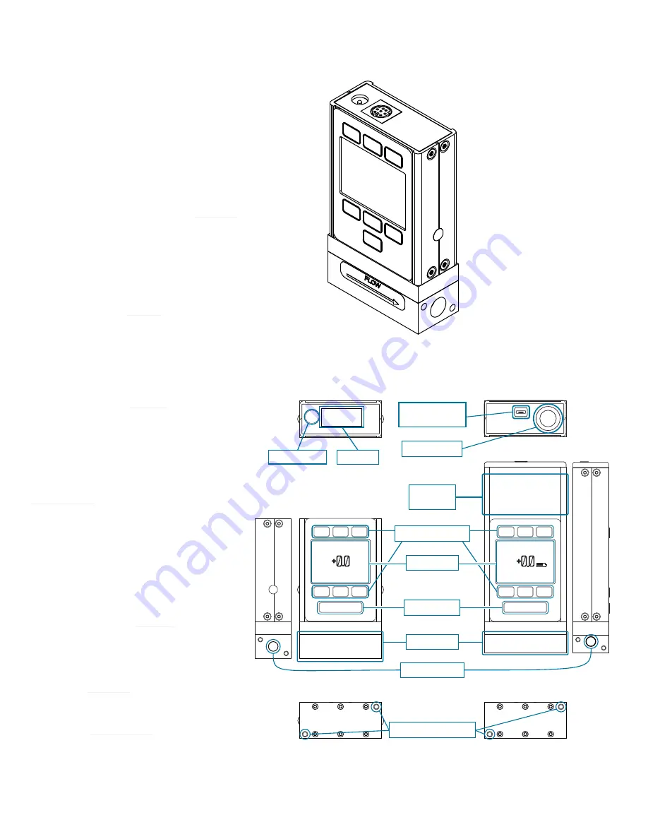
Connectors and Buttons
The drawing to the right represents a
typical configuration of a standard mass
flow meter.
Your device’s appearance
and process connections may differ.
See
page 12<DT>
for more examples.
Backlight
The monochrome display comes equipped
with a backlight.
To toggle the backlight
power, press the logo on the front of
your device.
For optional color TFT displays, pressing
this button will turn off the display to
conserve power. See
page 11
.
Maintenance and Care
•
Flow meters do not require cleaning
when flowing clean, dry gases. Read
more on
page 23
.
•
Calibrate your flow meter annually. To
schedule a calibration, please contact
support (
page 12<DT>
).
+0.0
+0.0
+13.49 +22.73
Mass Flow
CCM
SCCM
MENU
PSIA
¤C
TARE
FLOW
SCCM
A ir
+0.0
+0.0
+13.49 +22.73
Mass Flow
CCM
SCCM
MENU
PSIA
¤C
TARE
FLOW
SCCM
A ir
Mounting holes
Softkey buttons
Power input
Data I/O
Micro-USB
(data & power)
Power switch
Enclosed
battery
Meters
(M-Series)
Battery-Powered Meters
(MB-Series)
Display
Process ports
Flow body
Light button
This M-20SLPM-D model mass
flow meter is a typical unit. The
flow body can vary significantly,
generally depending on
full-scale flow rate.


