APB-DynaSonics ProDesk-4 Owner'S Manual Download Page 31

ProDesk-4 OWNER’S MANUAL

31

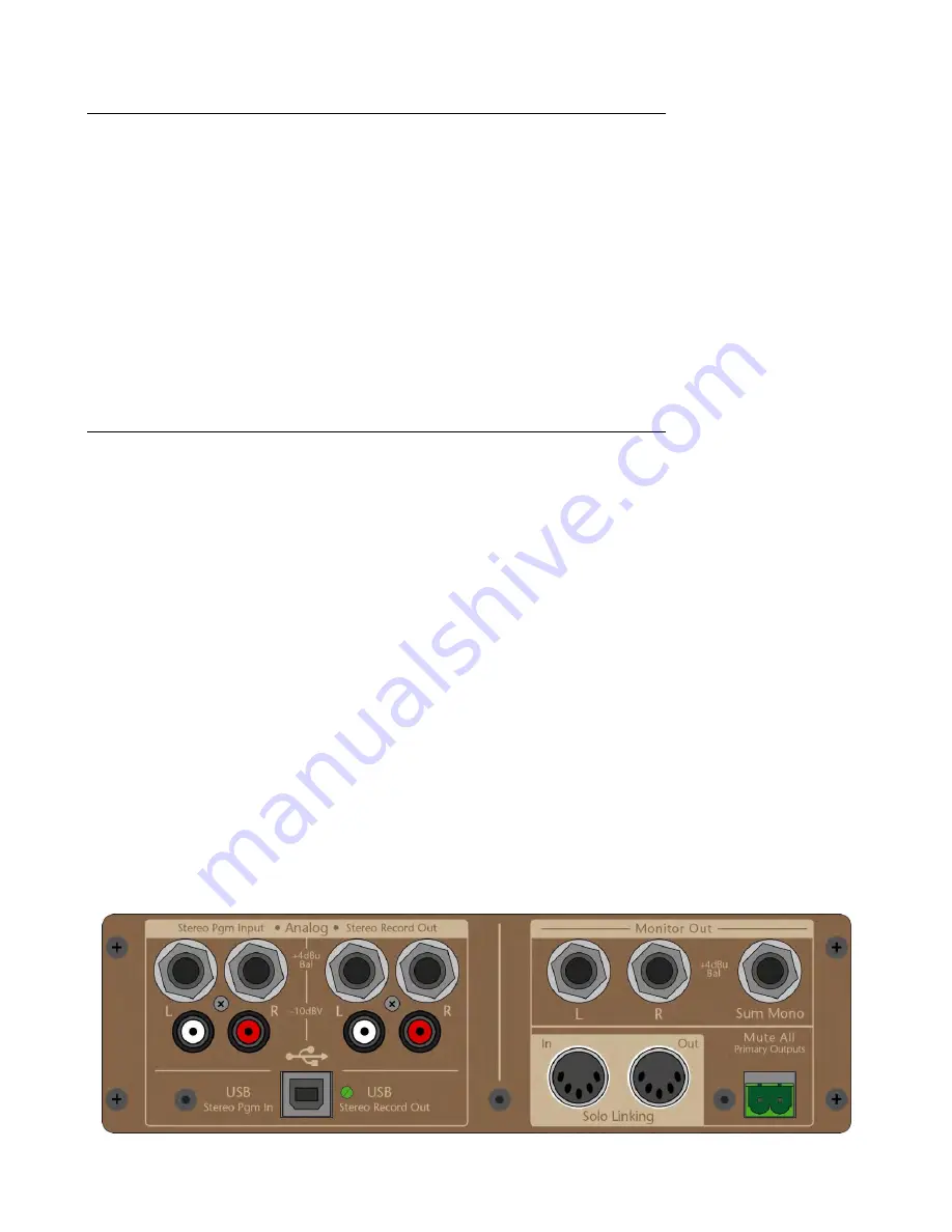
REAR PANEL CONNECTIONS for Stereo Program In and Stereo Record Out

Most connections for the Stereo Program Input and Stereo Record Out are located on this Master Interface Panel (shown
below). The only additional connection for the Stereo Program In is the Top Analog mini jack located on the Master Module
top panel.

Stereo Program Input: 1/4” TRS Balanced Input + RCA Unbalanced Input

These connectors are the “Rear Analog” source for the Stereo Pgm Input. Both sets of connectors can be used simultaneously;
the TRS and RCA signals will be mixed together and available as a single stereo source.

If only a mono source is available, plugging into just the Left TRS jack will feed both the left & right circuits; the right TRS jack
is connected to the left jack through its normalling contacts. Inserting a plug into the right jack will break this normalled
connection. There is no such normalling for the RCA jacks; use a Y-cord if a mono signal needs to feed both left & right sides.

Stereo Record Out: 1/4” TRS Balanced RCA Unbalanced Output

These connectors are fed from the Stereo Record Output circuitry. Both sets of connectors can be used simultaneously.

The TRS output is impedance-balanced with an output impedance of 200 Ω; design level is +4dBu

The RCA outputs are unbalanced, 1k Ω and are designed to feed a 10KΩ or higher load; design level is –10dBV

USB Audio In & Out

The ProDesk-4 will appear as a USB-peripheral to your computer; there is on onboard circuitry (CODEC) that allows 2-way
stereo communication via USB. Simultaneous record and playback of audio is possible using commonly available software.
Note: CODEC is the term for an enCOder/DECoder. A single CODEC chip is used in the ProDesk for bi-directional USB
conversion and communication: Burr-Brown PCM2900. A USB B-Type connector is provided.

The USB Audio Out (to the computer) can be driven from the same audio signals feeding the Stereo Record Out; the top
panel USB-On switch will feed that audio to the input of the CODEC.

USB Audio In (from the computer) can feed the Stereo Program In section (top panel switch labeled Rear USB) and also feeds
the alternate input of Stereo Input D.

When plugged into the USB port of a computer, the ProDesk will show up as a “USB Audio CODEC” in both Windows and Mac
OS X. Use the “System Preferences- Sound” (OS X) or “Control Panel- Sounds and Audio Devices” (Windows) to select the
ProDesk as your Input or Output device and to adjust any system-controlled parameters (balance & volume).

By default, the internal CODEC is bus-powered by the computer’s USB port; the LED will illuminate when power is available
for the CODEC chip. The analog electronics surrounding the CODEC chip is console-powered for best performance and
headroom. The CODEC is capable of stereo, 16-bit operation at 33, 44, and 48kHz sample rates. The computer sets all CODEC
parameters; there are no user controls on the console itself. When used without additional program support, the CODEC
defaults to the system-level settings of the computer itself. When used with a recording or editing program, the sample rate,
word length and other parameters of the CODEC are controlled by that program.

With just the computer’s system-level controls, you will be able to select “USB Audio CODEC” from the list of audio devices as
the output source for playback of recorded sounds, songs and cues from the computer.
Any of the recording/editing programs available can use the “USB Audio CODEC” as the input source for direct recordings
from the Console (via the Stereo Record Out section).

Suggested (free) audio editing program: Audacity (for Mac, Win and Linux)
Download at: http://audacity.sourceforge.net/download/

Master Interface Panel

(On rear of console)

Summary of Contents for ProDesk-4

Page 1: ...ProDesk 4 OWNER S MANUAL APB DynaSonics Inc 20 West End Road Totowa New Jersey 07512 U S A Tel 973 785 1101 Fax 973 785 1105 Web www apb dynasonics com...

Page 2: ...APB DynaSonics 2...

Page 3: ...duce heat 10 Do not defeat the safety purpose of the polarized or grounding type plug A polarized plug has two blades with one wider than the other a grounding type plug has two blades and a third gro...

Page 4: ...NDS 20 STEREO LINE INPUT MUTE SOLO AND LEVEL CONTROL 21 STEREO LINE INPUT BUS ASSIGNMENT AND BALANCE 22 STEREO LINE INPUT REAR PANEL CONNECTORS 23 MASTER SECTION 24 AUXILIARY BUSES 1THRU 6 24 GROUP OU...

Page 5: ...TEXT THAT FOLLOWS AND HAVE THE FOLLOWING MEANINGS TO AVOID ELECTRIC SHOCK FOLLOW THE INSTRUCTION NEXT TO THIS SYMBOL TO AVOID AN UNSAFE CONDITION FOLLOW THE INSTRUCTION NEXT TO THIS SYMBOL PSU A PSU...

Page 6: ...openings must not be covered while the system is on Low noise internal fans provide air movement OPERATION Turn on each power supply using the rocker switch on the PS panel Normal operation is signale...

Page 7: ...EMENT OF POWER SUPPLY UNITS 1 Disconnect the AC power cord 2 Remove four screws that secure the PS unit in the console chassis marked with the symbol in the diagram Pull on the power supply handle and...

Page 8: ...d unsafe internal temperature Approvals USA Recognized power supply with ETL marking and listing USA and Canada UL60065 7th Edition Electrical Safety Europe EN60065 7th Edition Electrical Safety Europ...

Page 9: ...y questions or comments about this APB DynaSonics product please do not hesitate to contact us at Tel 973 785 1101 Fax 973 785 1105 e mail info apb dynasonics com Manual Scope This manual is not inten...

Page 10: ......

Page 11: ...ll step to next mode LED will change color If MODE switch is not re pressed when LED is still illuminated meter status remains in its current mode STATUS LED Additional Function If Mute All is activat...

Page 12: ...ted XLR or 1 4 Polarity Reverse Switch When depressed reverses the electrical input polarity of any microphone or line level input signal Use of this control may alter the sound quality of an input re...

Page 13: ...gh mid frequency band EQ between 400Hz and 8kHz The bandwidth is approximately one octave High Mid Level Control Adjust the high mid band boost cut between 15dB there is a detent at the center 0 posit...

Page 14: ...the Aux Pre Source select switch above Aux 1 2 Stereo Switch Reconfigures the individual Aux 1 and 2 controls from two level controls to a Pan control 1 and a Level control 2 This enables a stereo mi...

Page 15: ...e sample points in the channel s signal path approach within 3dB of clipping Please Note The overall channel meter should be considered as 2 separate monitoring indicators the Green and Yellow LEDs ar...

Page 16: ...ems this bus can be used as the primary output leaving the L R output available for stereo recording It is usually used in LCR installations to feed a discrete signal to the center speaker It may also...

Page 17: ...d has an output impedance of 100 unbalanced and the insert return has an input impedance of 5k unbalanced Operating level is 4dBu NOTE The user should ensure that any device inserted into the channel...

Page 18: ...Pre Aux Feed Aux Send Blend Control When the Split Track mode switch is pressed the Pre Aux Feed control will be active This control allows the operator to adjust the mono mixture of the left right in...

Page 19: ...y Level Control Bell shape Adjusts the high mid frequency bell shaped cut boost between 15dB Use of this EQ control will affect both the left and right signal paths The Low Mid EQ has a center frequen...

Page 20: ...If Split Track is active both of the sends receive the same mono mix from the either the Pre fader Blend control when in Post or the Pre Aux Feed control when in Pre Aux Level Control 3 Adjusts the le...

Page 21: ...luminate without first having the Yellow LED lit This usually will be caused by excessive preamp levels and a subsequent cut in the EQ or there may be a compressor or limiter in the channel s insert p...

Page 22: ...nt Switch Assigns the post fader summed channel signal to the Center mix bus In mono sound systems this bus can be used as the primary Center output leaving the L R output available for stereo recordi...

Page 23: ...w signal into the Right side of the channel Left And Right RCA Input Connectors Provides for unbalanced line level inputs to the channel s left and right inputs Design level is 10dBV Input impedance i...

Page 24: ...the monitoring and meter system in mono both L R sides of the solo system are fed When both Aux 1 Aux 2 AFL buttons are pressed Aux 1 will feed the left solo bus while Aux 2 will feed the right solo...

Page 25: ...gnal levels on the associated Group mix bus Varying intensity Green indicates proper bus levels while red indicates approaching overload within the Group circuitry Overload is sensed after the mix amp...

Page 26: ...associated Left Right Center and Mono signals being fed into the associated matrix system A single switch in the Main output section above the Center fader determines if these signals are derived pre...

Page 27: ...fader feed Fader Flip Swap Mono Aux 6 controls This function is described earlier and in more detail in the Aux Master section The 3 controls and indicators for the Mono bus bi color sig LED 100mm fa...

Page 28: ...ssing or effects electronics can be inserted into the bus signal path after the summing amp Examples of external devices include additional equalization notch filters compressors limiters etc The iner...

Page 29: ...more information about the USB features on the ProDesk Stereo EQ High Low Freq EQ is available to adjust the tonal balance of the selected mixed input sources Both controls have a shelving response Hi...

Page 30: ...des M The Main Mono bus Mono bus feeds both left right sides Mtx 1 2 Matrix bus 1 2 Matrix 1 feeds left side Matrix 2 feeds right side Aux 1 2 Aux bus 1 2 Aux 1 feeds left side Aux 2 feeds right side...

Page 31: ...n and communication Burr Brown PCM2900 A USB B Type connector is provided The USB Audio Out to the computer can be driven from the same audio signals feeding the Stereo Record Out the top panel USB On...

Page 32: ...en this switch is depressed the monitor out is summed to a mono signal When this button is Up the sources maintain their stero images Headphone Level Control This control adjusts the level being fed t...

Page 33: ...ph faster attack Ave Peak Combination of both When both are active Peak shows as a single LED above an Averaging bargraph The same decay time is used for both to allow the Peak LED to always be visibl...

Page 34: ...tor to the selected buses TB On Master Talkback Switch internally illuminated This is a smart switch that will act as either a momentary or latching switch depending on how it is pressed Momentary Pre...

Page 35: ...ith a single external command This feature can be used when the PA system is required to be silenced during safety announcements or if a system wide mute is needed for any reason The 2 pin Phoenix con...

Page 36: ...re accessed by removing the Master Interface Panel to gain access to and adjust the position of the 4 removable jumpers Remove the 4 corner screws Philips head and pull the complete Interface assembly...

Page 37: ...r Inp Inp Mstr Inp Inp Inp Inp Inp Mstr Inp Inp Inp Inp Inp Mstr Inp Inp Inp Length L2 Inch mm 30 72in 780 3mm 38 82in 986 1mm 46 92in 1191 8mm 55 02in 1397 5mm 63 12in 1603 3mm Weight lbs kg 90 41 10...

Page 38: ...dB Channel Routing 80dB Channel Pan Isolation 80dB Channel to Channel Isolation 90dB Aux Send Attenuation 90dB Aux Pan Isolation 70dB Input Output Impedances Channel XLR Input 3K Balanced with or with...

Page 39: ...ProDesk 4 OWNER S MANUAL 39...

Page 40: ...APB DynaSonics ProDesk 4 Owners Manual Rev 0 91 July 2009...

Reviews: