background image

18

3

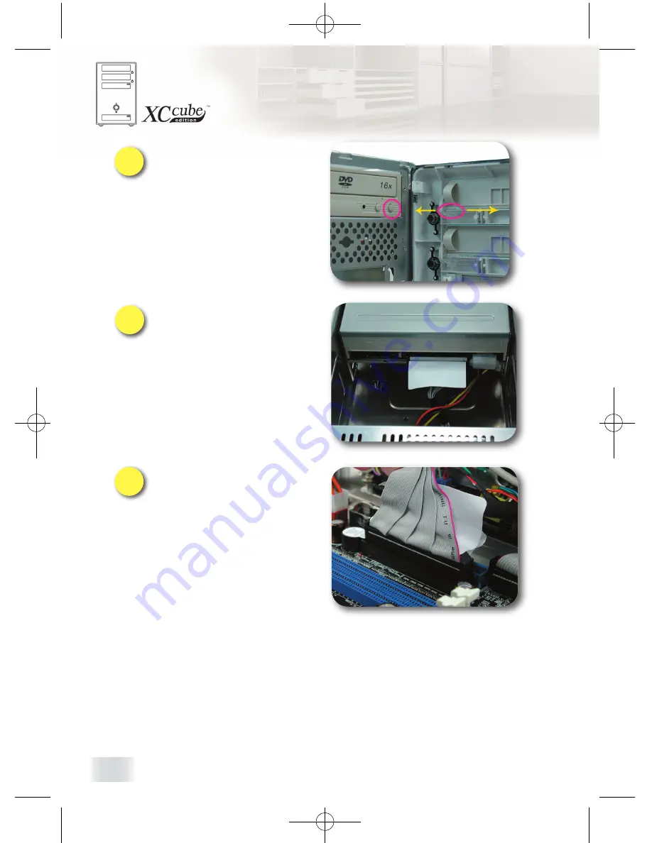
To  stand  on  your  deject  button 
position of the Optical drive, you can 
adjust  the  deject  lever  position  of 
the XC Cube Front Panel. It makes 
you to press the deject button of the 
Optical drive accurate.

4

When  you  install  the  cable  and 
power  cord  of  the  Optical  drive 

40pin,  please  pay  attention  to 
the  red  cable  should  aline  with 
the Optical drive and pin 1 of the 
Motherboard. As the functions of 
the Audio Digital or Audio Analog, 
please refer to your manual of the 
Optical drive.

5

You can connect the other side of the 
Optical drive 40pin cable and IDE 

hander of the Motherboard. Please 
pay attention to the red cable should 
aline with the Optical drive and pin 1 
of the Motherboard.

TZ65II̲915-OL-E0501A[49.BZ101.0A1].indd

2005/2/17, 下午 10:34

18

Summary of Contents for XC Cube TZ915

Page 1: ...2 8 Install CPU 2 8 1 Install CPU on Socket 478 20 2 8 2 Install CPU on Socket T 21 2 8 3 Install CPU on Socket 479 22 2 8 4 Install CPU on Socket A 23 2 8 5 Install CPU on Socket 754 24 2 8 6 Install CPU on Socket 939 25 2 9 Install CPU Cooler and CPU Fan Connector 26 2 10 Connecting DRAM to DIMM Sockets 26 2 11 Insert AGP card or PCI card to motherboard 27 2 12 Connect Keyboard and Mouse 28 2 13...

Page 2: ...nd other countries All the titles of the products and the trademarks mentioned in this manual are for the purpose of illustrative conveniences and are possessed by their respective firms We regret not informing about any changes in usage standards and other related information AOpen Company reserves the right of altering or modifying the content of this manual In case of any mistakes or incorrect ...

Page 3: ...I Getting Start TZ65II 915 OL E0501A 49 BZ101 0A1 indd 2005 2 17 下午 10 32 3 ...

Page 4: ... to the quality of all our products This manual is for those who want to set up computer by themselves In other words this is a book for Fresh drivers on the road If you are already a veteran this manual may not be suitable for you It is our hope that novices can build up their own computer step by step Now we would like to invite you to personally experience this user friendly manual and all of t...

Page 5: ... explains profound theories in simple language by colorful illustrations Therefore you will see the icons below frequently Contains knowledge you should know in process of assembling or some helpful tips Note Mark Warning Mark Please be careful when you see this mark It highlights mistakes that occur often during assembling or something you need to pay attention to Force direction This arrow shows...

Page 6: ...hands Some screw holes are placed where hands can hardly reach At this time we need a magnetic screwdriver too In addition the size of our tool also matters Generally the domestic 107 cross screwdriver is the most appropriate one Besides a flat screwdriver is also essential for installing CPU on socket 479 When putting things together it is necessary to adjust Jumper In most cases things can be do...

Page 7: ...ou will find components as follow XC Cube chassis Drives Cage Motherboard Pre installed on XC Cube chassis Power Supply Pre installed on XC Cube chassis CPU cooler XC Cube User s Manual XC Cube Easy Installation Guide CPU cooler TZ65II 915 OL E0501A 49 BZ101 0A1 indd 2005 2 17 下午 10 32 7 ...

Page 8: ...rew s threads are wide as well but it has a round head As shown in the picture threads on NO 2 screw are narrow and there is a ring on its head IDE Cable a 40 pin connector to connect the hard disk with IDE interface IDE Cable a 40 pin connector to connect the optical device IDE interface Disk Drive Cable a 34 pin connector to connect disk drive As shown in the picture the NO 4 screw s threads are...

Page 9: ...II Start To Assemble TZ65II 915 OL E0501A 49 BZ101 0A1 indd 2005 2 17 下午 10 32 9 ...

Page 10: ...es with your mood Space flexibility allows you to move it from living room or to your bedroom Silent Technology PC that is quiet even in the middle of the night Easy Installation for any new hand assembling their first PC Mini housing which saves you almost 60 of housing space Hand harmlessness design ensures you 100 security during assembling Equipped with a highly efficient power supply to keep ...

Page 11: ...alling 1 Unscrew all screws on the chassis Use your thumb to push the chassis backward to you 2 Lift the chassis up Here you may see the internal of the chassis TZ65II 915 OL E0501A 49 BZ101 0A1 indd 2005 2 17 下午 10 32 11 ...

Page 12: ...p of the both side panel As the left picture shown the first you can pull it apart toward the both side then softly pull it away Finally you can pull the Front Panel apart Be careful not to break the rib 3 Take the Front Panel from top of it TZ65II 915 OL E0501A 49 BZ101 0A1 indd 2005 2 17 下午 10 32 12 ...

Page 13: ...ong the curve slideway 2 Put the Hard disk into the Hard disk bay please pay attention to the yellow arrowhead as shown and take the PCB Printed Circuit Board of the Hard disk toward up The purpose of the purple mark is to remind you put the connecter of the Hard disk toward outside That will be the same direction with the screw 3 TZ65II 915 OL E0501A 49 BZ101 0A1 indd 2005 2 17 下午 10 32 13 ...

Page 14: ... it Don t remove the cover because it will help you to install correct next time 4 It takes the Hard disk bay back to the Drive Cage along the curve slideway and then locks the screw tightly 5 When you install the cable and power cord of the Hard disk 40pin please pay attention to the red cable should aline with the Hard disk and pin 1 of the Motherboard 6 TZ65II 915 OL E0501A 49 BZ101 0A1 indd 20...

Page 15: ...k 1 As Serial ATA hard disk comes with different power connector and Serial ATA cable please use our bundled SATA power connector and Serial ATA cable to connect the hard disk 2 If you happen to have Serial ATA hard disk this motherboard comes with Serial ATA connectors onboard as well With EzColor design you may easily find out the correct flame red cable with the correct header You may kindly in...

Page 16: ... and Card reader must display on the Front Panel then the user can easy to use it So the no 1 screw aperture of the FDD sign can aline the Front Panel If you have the other kinds of the 3 5 device need to use you can stand on the length of the device to choose the suitable screw aperture When you install the cable and power cord of the Floppy disk 34pin please pay attention to the red cable should...

Page 17: ...he Motherboard If you install the Card reader you can connect the cable to the USB hander of the Motherboard 1 Install Optical drive to the first Drive bay of the 5 25 Drives Cage Then make the Front Panel of the Optical drive aline front of the Motherboard 2 You can stand on the length of the Optical drive and then use the screw no 2 to screw it tightly TZ65II 915 OL E0501A 49 BZ101 0A1 indd 2005...

Page 18: ...pin please pay attention to the red cable should aline with the Optical drive and pin 1 of the Motherboard As the functions of the Audio Digital or Audio Analog please refer to your manual of the Optical drive 5 You can connect the other side of the Optical drive 40pin cable and IDE hander of the Motherboard Please pay attention to the red cable should aline with the Optical drive and pin 1 of the...

Page 19: ...w order It will make the XC Cube TZ Series have more thermo performance and expandability If you would like to set up the others device please follow the step as below to take the Front Panel apart 3 5 Hard Disk No 4 3 5 Hard Disk No 2 3 5 Hard Disk No 3 3 5 Hard Disk No 1 5 25 Optical Drive No 1 5 25 Optical Drive No 2 TZ65II 915 OL E0501A 49 BZ101 0A1 indd 2005 2 17 下午 10 34 19 ...

Page 20: ...erect CPU socket lever up Then install CPU onto CPU socket 2 Press the lever back to CPU socket The purpose of this chapter introduces how to set up different kinds of the CPU The Motherboard of the shown is just an example The real object that you bought is stand on Motherboard of the XC Cube TZ65II 915 OL E0501A 49 BZ101 0A1 indd 2005 2 17 下午 10 34 20 ...

Page 21: ...ic cap and erect CPU socket lever up 2 Pull CPU socket plate up and install CPU onto CPU socket Then press plate back to CPU socket 3 Press down CPU socket lever to finish CPU installation TZ65II 915 OL E0501A 49 BZ101 0A1 indd 2005 2 17 下午 10 34 21 ...

Page 22: ...icator on socket screw aims at open direction the default is open Plastic membrane Socket screw Drop shaped indicator Match socket Pin 1 and golden arrow and gently put CPU onto CPU socket Then lock socket screw clockwise to finish CPU installation 2 TZ65II 915 OL E0501A 49 BZ101 0A1 indd 2005 2 17 下午 10 34 22 ...

Page 23: ...3 2 8 4 Install CPU on Socket A 1 Erect CPU socket lever up and gently put CPU onto Socket 2 Press lever back to CPU socket and then it s done TZ65II 915 OL E0501A 49 BZ101 0A1 indd 2005 2 17 下午 10 34 23 ...

Page 24: ... 2 8 5 Install CPU on Socket 754 1 Erect CPU socket lever up and gently put CPU onto Socket 2 Press lever back to CPU socket and then it s done TZ65II 915 OL E0501A 49 BZ101 0A1 indd 2005 2 17 下午 10 35 24 ...

Page 25: ... 2 8 6 Install CPU on Socket 939 1 Erect CPU socket lever up and gently put CPU onto Socket 2 Press lever back to CPU socket and then it s done TZ65II 915 OL E0501A 49 BZ101 0A1 indd 2005 2 17 下午 10 35 25 ...

Page 26: ...or optimized air flow performance within chassis For details please refer to Easy Installation Guide 2 10 Connecting DRAM to DIMM Sockets DIMM socket is designed in Sky Blue color which is very easy to recognize Install memory module evenly into DIMM TZ65II 915 OL E0501A 49 BZ101 0A1 indd 2005 2 17 下午 10 35 26 ...

Page 27: ...u may insert them onto the slot as shown Screw the iron plate off the back panel and use the screwdriver to pry it out 1 After that please plug in the AGP PCI Express x16 card Screw the iron lock on top of the AGP slot will do 2 PCI card is done 3 TZ65II 915 OL E0501A 49 BZ101 0A1 indd 2005 2 17 下午 10 35 27 ...

Page 28: ...28 2 12 Connect Keyboard and Mouse 2 13 Connect Monitor and tighten screws 2 14 Connect Microphone Speaker or Earphone and Network cable TZ65II 915 OL E0501A 49 BZ101 0A1 indd 2005 2 17 下午 10 35 28 ...

Page 29: ...y power outlet differs from countries or areas you dwell in If the outlet is supplied by 110V please set the switch to 115V If the outlet is supplied by 220V please set the switch to 230V Connect Power Cord Cable finally TZ65II 915 OL E0501A 49 BZ101 0A1 indd 2005 2 17 下午 10 35 29 ...

Page 30: ...30 Note TZ65II 915 OL E0501A 49 BZ101 0A1 indd 2005 2 17 下午 10 35 30 ...

Page 31: ...III Turn On The Power TZ65II 915 OL E0501A 49 BZ101 0A1 indd 2005 2 17 下午 10 35 31 ...

Page 32: ...ve done so far Now take a short break and have a drink Then turn on the computer to see how things are going 3 2 Set BIOS Basic Input Output System 1 Not long after activating the power you ll see the following screen Please press Delete button to get into BIOS If you would like to see the POST screen you may just press Tab button TZ65II 915 OL E0501A 49 BZ101 0A1 indd 2005 2 17 下午 10 35 32 ...

Page 33: ...ll see the following BIOS setup 3 Now you can move the cursor by using direction keys on the keyboard Move the cursor to the option item Load Setup defaults and press Enter TZ65II 915 OL E0501A 49 BZ101 0A1 indd 2005 2 17 下午 10 35 33 ...

Page 34: ... up to confirm the default BIOS values Please press Y to confirm and then press Enter 4 Finally move the cursor to Save Exit Setup and press Enter to save the parameters and exit BIOS setup TZ65II 915 OL E0501A 49 BZ101 0A1 indd 2005 2 17 下午 10 35 34 ...

Page 35: ...35 5 At the same time type Y in the dialogue box and press Enter to exit Now everything is perfectly finished TZ65II 915 OL E0501A 49 BZ101 0A1 indd 2005 2 17 下午 10 35 35 ...

Page 36: ...an find all varieties of books with comprehensive introduction in bookstores Having a computer of your own is a beginning to the era of information If this computer is assembled yourself it is uniquely meaningful to you Through our introduction you have learned the key components a computer needs and what details you need to pay attention to when assembling We sincerely hope every customer who wan...

Page 37: ...P or Windows 98SE ME 1 Power on and then press Delete to enter BIOS during POST Power On Self Test 2 Select Integrated Peripherals SIS OnChip PCI Device SiS Serial ATA Mode 3 For installing Windows 2000 XP please select IDE mode Floppy drive is not necessary 4 For installing Windows 98SE ME please select RAID mode Floppy Drive is not necessary but make sure FDD is disabled in BIOS or FDD is correc...

Page 38: ...re starting to install OS Of course user needs to install two Serial ATA hard disks to motherboard too First start OS installation and then press F6 while you are presented with the sentence Press F6 if you want to install a third party SCSI or RAID driver Press S when Windows Setup is generated Then insert SiS 964 RAID driver diskette into Floppy and press Enter 1 2 Press F6 if you need to instal...

Page 39: ...OS Windows 2000 or Windows XP and press Enter to install the driver 4 For more information of RAID installation please refer to the file 964_180umh030 pdf in the Utility CD TZ65II 915 OL E0501A 49 BZ101 0A1 indd 2005 2 17 下午 10 36 39 ...

Page 40: ...P14 to its normal setting by shorting pin 1 pin 2 5 Connect ATX power cable back to connector PWR2 JP14 Clear CMOS Normal default Clear CMOS 1 1 Pin 1 JP28 Keyboard Mouse Wakeup Jumper You can use JP28 to enable or disable this function which could resume your system from suspend mode with keyboard or mouse The factory default setting is Disable 1 2 and you may enable this function by setting the ...

Reviews: