Secondary
Slave (4th)
Primary
Master (1st)
Primary
Slave (2nd)
Secondary
Master (3rd)
Pin 1
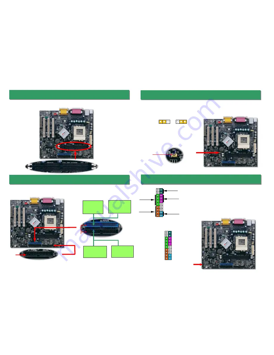
7. Connecting IDE and Floppy Cable
6. Install DIMM Modules
8. JP13 LAN Select Jumper (MX36LE-UN Only)
9. Connecting Front Panel Cable
Connect 34-pin floppy cable and 40-pin IDE cable to floppy connector FDC and IDE
connector. The
blue connector
is IDE1 for clear identification. Be careful of the pin1
orientation. Wrong orientation may cause system damage.
This jumper allows you to enable or disable the LAN onboard function by adjusting the
position of yellow cap.
DIMM1
DIMM2
IDE2 (Secondary)
Pin 1
IDE1 (Primary)
FDD Connector
IDE Connector
Attach the power LED, ACPI, speaker, power and reset
switch connectors to the corresponding pins. If you enable
“Suspend Mode” item in BIOS Setup, the ACPI & Power
LED will keep flashing while the system is in suspend
mode.
Locate the power switch cable from your ATX housing. It is
2-pin female connector from the housing front panel. Plug
this connector to the soft-power switch connector marked
SPWR
.
This motherboard has two 168-pin DIMM sockets that allow you to install PC100 or
PC133 memory up to 1.0GB.
Pin 1
Enable
Disable
1
1
1
Speaker
IDE LED
+
+
+
SPWR
+
ACPI &
Power LED
Reset
1
SPWR
GND
ACPILED-
GND
ACPILED
NC
NC
GND
RESET
GND
NC
NC
+5V
IDE LED
IDE LED
+5V
+5V
GND
NC
SPEAKER


