AOpen FORTLESS1100 Easy Installation Manual Download Page 3


Item 

Frequency 

128KB 

256KB 

512KB 

Coppermine

800MHz 

YES 

YES 

NO 

Coppermine

866MHz 

YES 

YES 

NO 

Coppermine

933MHz 

YES 

YES 

NO 

Coppermine

1GHz 

YES 

YES 

NO 

Coppermine

1.13GHz 

YES 

YES 

NO 

Coppermine

1.26GHz 

YES 

YES 

NO 

Tualatin 

1GHz 

NO 

YES 

YES 

Tualatin 

1.13GHz 

NO 

YES 

YES 

Tualatin 

1.20GHz 

NO 

YES 

YES 

Tualatin 

1.26GHz 

NO 

YES 

YES 


CPU 

CPU Core 

Frequency 

FSB Clock 

Ratio 

Pentium III 800E 

800MHz 

100MHz 

8x 

Pentium III 850E 

850MHz 

100MHz 

8.5x 

Pentium III 533EB 

533MHz 

133MHz 

4x 

Pentium III 600EB 

600MHz 

133MHz 

4.5x 

Pentium III 667EB 

667MHz 

133MHz 

5x 

Pentium III 733EB 

733MHz 

133MHz 

5.5 

Pentium III 800EB 

800MHz 

133MHz 

6x 

Pentium III 866EB 

866MHz 

133MHz 

6.5 

Pentium III 933EB 

933MHz 

133MHz 

7x 

Pentium III 1G 

1GHz 

133MHz 

7.5x 

Pentium III 1.13G 

1.13GHz 

133MHz 

8.5x 

Pentium III 1.26G 

1.26GHz 

133MHz 

9x 

5. Setting CPU Voltage & Frequency 

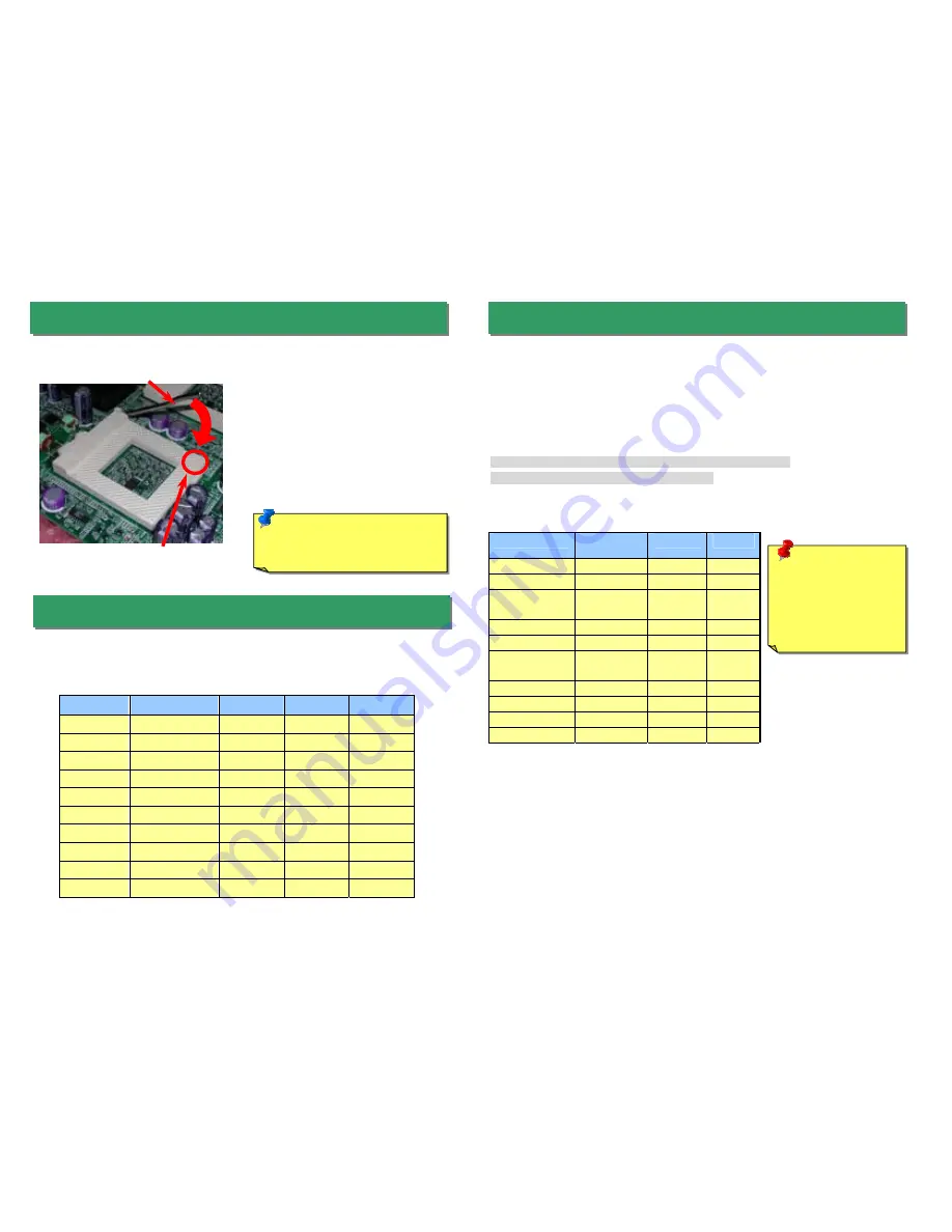
3. Installing Processor 

4. Supported CPU Type 

Note: 

If you do not match the CPU 

socket Pin 1 and CPU cut edge 
well, it may damage the CPU. 

CPU socket lever 

CPU Pin 1 and cut edge 

1. 

Pull up the CPU socket lever and up to 
90-degree angle.


2. 

Locate Pin 1 in the socket and look for a 
(golden) cut edge on the CPU upper 
interface.


Match Pin 1 and cut edge. 

Then insert the CPU into the socket.


3. 

Press down the CPU socket lever and 
finish CPU installation.


Setting CPU Core Voltage


This motherboard supports CPU VID function. The CPU core voltage will be automatically 
detected and the range is from 1.05V to 1.825V. It is not necessary to set CPU Core Voltage


Setting CPU Frequency 

This motherboard is CPU jumper-less design, the system can detect the CPU frequency 
automatically, and no jumpers or switches are needed. 


BIOS Setup > Frequency / Voltage Control > CPU Speed Setup


Core Frequency = CPU FSB Clock * CPU Ratio 

Warning:

 We strongly 

recommend you do 
not overclocking your 
CPU and system for 
get more system 
reliability.


Fortress1100 supports one Coppermine (up to 1 GHz with 256 L2 cache) or Tualatin 
(up to 1.26 GHz with 512K L2 cache) processor with external FSB up to 133 MHz. 

Summary of Contents for FORTLESS1100

Page 1: ...100 IDE Connector 32 Bit PCI Slot x 2 FAN3 Connector FAN1 Connector 100W PFC Switching Power supply Slim type CD ROM drive JP5 VGA IRQ Jumper RJ45 Jack RJ45 Jack VGA Connector Power supply Fan Sensor VIA VT82C686B SB IPMI ROM System FLASH BIOS RAID Channel x2 CD ROM Connector System FAN 370 pin CPU Socket with Voltage Frequency Auto detection supports Intel Pentium III Both Coppermine Tualatin are...

Page 2: ...on a complete Online User s Manual can be found in the Bonus Pack CD Disc Thanks for the help of saving our earth PART NO 90 53F30 001 DOC NO SX34 EG E0112A Note Some CPU fans do not have sensor pin so they cannot support fan monitoring Fan2 Connector 2 Installing CPU System Fan FAN1 Connector FAN4 Connector FAN3 Connector You can clear CMOS to restore system default setting To clear the CMOS foll...

Page 3: ...the CPU socket Pin 1 and CPU cut edge well it may damage the CPU CPU socket lever CPU Pin 1 and cut edge 1 Pull up the CPU socket lever and up to 90 degree angle 2 Locate Pin 1 in the socket and look for a golden cut edge on the CPU upper interface Match Pin 1 and cut edge Then insert the CPU into the socket 3 Press down the CPU socket lever and finish CPU installation Setting CPU Core Voltage Thi...

Page 4: ... RAID or ATA interface The default setting is IDE RAID The system is equipped with an intrusion alarm device Whenever the opening of the chassis triggers the sensor the system will send out beep sound to inform you The connector is equipped with a foolproof device This jumper allows you to decide to power on by south bridge or IPMI The default setting is By IPMI 1 IDE RAID default 1 ATA 1 Disable ...

Page 5: ...l of the pin1 orientation Wrong orientation may cause system damage 13 Installing DIMM Sockets 1 Disable default 1 Enable Dimm1 Dimm3 Dimm2 The ATX power supply uses 20 pin connector shown below The connector is equipped with a foolproof device Make sure you plug in the right direction Floppy drive connector ATA 100 IDE connector RAID secondary channel CD ROM drive connector RAID primary channel T...

Page 6: ...indicates the transfer mode and it lights when data is transferring in 100Mbps mode To enable or disable this function you may simply adjust it through BIOS Green ACT Orange Speed The picture shown below indicates the functions of all connectors on the real panel The connectors are all different in their shape or color They all have foolproof devices Please make sure you plug in the right directio...

Page 7: ...IOS Setup Choose Load Setup Default The problem should be caused by the IDE cables or HDD itself Re install Windows 95 Windows 98 or Windows NT Yes Yes Turn off the power and unplug the AC power cable then remove all of the addon cards and cables including VGA IDE FDD COM1 COM2 and Printer Turn on the power and check if the power supply and CPU fan work properly Start Check if there is display Pre...

Page 8: ...e news group probably had answered your problem http www aopen com tech newsgrp default htm 4 4 Contact Distributors Resellers We sell our products through resellers and integrators They should know your system configuration very well and should be able to solve your problem more efficiently and provide important reference for you if next time you want to buy something else from them 6 6 Contact U...

Reviews: