


There are four system FAN connectors provided by Fortress1100 system. Each of them is a 3-pin
connector, which brings the failure report, 12V power and ground. The system FAN is designed with
redundancy to prevent thermal disaster caused by FAN failure.
U
ser Manual x 1
IDE ATA Cable x 2
Heat-sink x 1
Screw Package (10 HDD Screws)
Bonus Pack CD x 1
This Easy Installation Guide x 1
One set rubber feet (4)
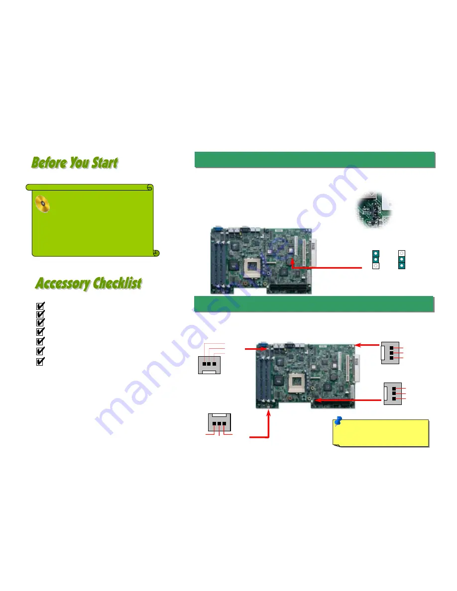
1. JP3 Clear CMOS
Everything you need to boot this
motherboard is included in this
Easy Installation Guide. For more
information, a complete
Online
User's Manual
can be found in the
Bonus Pack CD Disc
. Thanks for
the help of saving our earth.
PART NO: 90.53F30.001
DOC. NO: SX34-EG-E0112A
Note:
Some CPU fans do not have
sensor pin so they cannot support fan
monitoring.
Fan2 Connector
2. Installing CPU & System Fan
FAN1 Connector
FAN4 Connector
FAN3 Connector
You can clear CMOS to restore system default setting. To
clear the CMOS, follow the procedure below.
1. Turn off the system and unplug the AC power.
2. Remove ATX power cable.
3. Locate JP3 and short pins 2-3 for a few seconds.
4. Return JP3 to its normal setting by shorting pin 1 & pin 2.
5. Connect ATX power cable back.
1
Normal
(default)
1
Clear CMOS
GND
+12V
SENSOR
GND
+12V
SENSOR
GND
+12V
SENSOR
GND
SENSOR
+12V


