background image

22

Englis

h

Englis

h

Englis

h

Englis

h

10. Digital Captions Setup: Provide 

numerous options for setting the digital 
closed caption style in the sub-menu.

  [Style] – Set to Automatic or Custom 

mode. If Custom mode is selected, user can 
modify the detail styles described below. The 
setting result will be shown immediately on 
the bottom of the sub-menu OSD. Note: 
This feature is only available in Digital TV 
(ATSC) mode.

  [Size] – Digital closed caption font size, 

which can be set as Automatic, Small, 
Normal or Large.

  [Font] – Digital closed caption font style, 

which can be chosen as Automatic, Default 
or Font 1 ~ 7.

  [Text Color] – Automatic / White / Red 

/ Green / Blue / Yellow / Magenta / Cyan / 
Black

  [Text Opacity] – Automatic / Solid / 

Flashing / Transparent / Translucent

  [Background Color] – Automatic / 

Black / White/ Red / Green / Blue/ Yellow / 
Magenta / Cyan

  [Background Opacity] – Automatic / 

Solid / Flashing / Transparent / Translucent

  [Edge Effect] – Automatic / None / Raised 

/ Depressed / Uniform / Left Shadow / Right 
Shadow

  [Edge Color] – Automatic / Red / Green 

/ Blue / Yellow / Magenta / Cyan / Black / 
White.

11. Input Labels: User can edit the input 

labels.

12. Component Setting: This option only 

shows and is available in component mode, 
which provides fine tuning component 
display.

  [Phase] – Adjust Picture Phase to reduce 

Horizontal-Line noise. The tuning range is 
from 0 to 100. 

  [Preset] – Restore the default component 

setting values.

13. Reset to Default: Restore all the default 

settings.

VGA MENU

This option only shows and is available in VGA 
mode, which provides several items for the 
VGA display fine tuning.

1. H-Position: Adjust the horizontal position 

of the picture. (0-100)

2. V-Position: Adjust the vertical position of 

the picture. (0-100)

3. Clock: Adjust picture clock to reduce 

Vertical-Line noise. (0-100)

4. Phase: Adjust Picture Phase to reduce 

Horizontal-Line noise. (0-100)

5. Auto Adjust: Adjust the settings 

automatically.

6. Preset: Restore the default VGA setting 

values.

Summary of Contents for L22W961

Page 1: ......

Page 2: ...NGYOUR LCD HDTV FOR WALL MOUNTING 6 PERIPHERAL CONNECTION GUIDE 8 OPERATING INSTRUCTIONS 9 TO USE THE FRONT PANEL CONTROL 9 TO USE THE REMOTE CONTROL 10 IEWING MODELS ILLUSTRATIONS 11 CONNECTING EQUIPMENT 12 TO USE THE MENUS 19 CHANNEL MENU 19 VIDEO MENU 19 AUDIO MENU 20 FEATURE MENU 20 VGA MENU 22 TIPS 23 PRODUCT SPECIFICATION 24 BEFORE CALLING SERVICE 25 GLOSSARY 26 English ...

Page 3: ...irán funcionando como antes para otros usos por ejemplo para ver emisoras de TV de baja potencia que todavía transmiten en analógico para ver películas pregrabadas o para utilizar sus videojuegos Para obtener más información llame FCC 1 888 CALL FCC 1 888 225 5322 o refiérase a www DTV gov Para toda información sobre el programa de conversores de TV y acerca de los cupones del gobierno que se pued...
Page 4: ...not occur in a particular installation If this equipment does cause harmful interference to radio or television reception which can be determined by turning the equipment off and on the user is encouraged to try to correct the interference by one or more of the following measures 1 Reorient or relocate the receiving antenna 2 Increase the separation between the equipment and receiver 3 Connect the...

Page 5: ... AC outlet before cleaning Do not use liquid cleaners or aerosol cleaners to clean the display Make sure to unplug the unit when not in use for a long period of time days Do not cover or block any vents and openings Inadequate ventilation may shorten the life of the display unit and cause overheating Avoid direct sunlight dusty high humidity and smoky areas Call service personnel to clean the inte...

Page 6: ...to apparatus the apparatus has been exposed to rain or moisture does not operate normally or has been dropped 15 The TV should be operated only from the type of power source indicated on the label If you are not sure of the type of power supplied to your home consult your dealer or local power company 16 Class I Protective Earthing Connection The Class I apparatus shall be connected to a mains soc...

Page 7: ...enna Grounding If an outside antenna is connected to the receiver be sure the antenna system is grounded so as to provide some protection against voltage surges and built up static charges Section 810 of the National Electric Code ANSI NFPA No 70 1984 provides information with respect to proper grounding of the mats and supporting structure grounding of the lead in wire to an antenna discharge uni...

Page 8: ... base to the stand PREPARINGYOUR LCD HDTV FOR WALL MOUNTING We suggest that you keep your TV at least 2 56 inches 65 mm from the wall to prevent cable interference Before mounting your TV on the wall you need to remove the base For your safety please use only with UL listed wall mount bracket with minimum weight of the TV without stand Please see page 24 To attach a wall mount bracket to your TV 1...

Page 9: ... a minute with display on the screen MUTE SOURCE Power Key Please make sure to connect the power plug to the wall outlet socket after connecting the TV to the power cord 1 Install the base stand place theTV on a solid surface Min 1 m Ensure that the TV is placed in a position to allow free flow of air Do not cover the ventilation openings on the back cover To prevent any unsafe situations no naked...

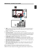
Page 10: ...w connector 4 COMPONENT Y Pb Pr with Audio L R Connect the primary source for component video devices such as a DVD Player or set top box here From left to right use red for Pr blue for Pb green forY red for right audio R and white for left audio L inputs 5 ANTENNA CABLE DIGITAL ANALOG Connect to an antenna or digital cable out of the wall not from Cable Box for Digital TV 6 SPDIF Optical Digital ...

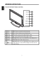
Page 11: ... level 3 CH CH Press to select the next higher Program number 4 CH CH Press to select the next lower Program number 5 MENU Menu key Press to open or exit the OSD on screen display menu 6 INPUT Source key Press to select the input source 7 i POWER Power key Press to turn on off standby the TV set Press to turn on TV after the power on status LED had changed to the Blue color and stopped flashing ...

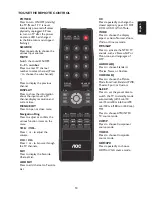
Page 12: ...wse through the TV channels FAV Press to display the Favorite Channel List ADD FAV Press to add channel to Favorite List CC Press repeatedly to change the closed caption type as CC Off CC On CC On With Mute WIDE Press to choose the display aspect as Auto Normal Zoom Wide or Cinema mode MTS SAP Press to activate the NTSC TV sounds such as Stereo SAP or Mono tone and languages of DTV AUDIO ADJ Press...

Page 13: ...n of the display 16 9 Content 4 3 Content ZOOM Mode For those wide format images which are originally programmed into 4 3 frames with black bars around this mode would stretch the image in both width and height for full display with active data Same image in ZOOM mode CINEMA Mode This mode is applied to view 2 35 1 format content on 16 9 displays Cropping on both right and left sides to keep the i...

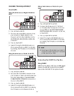
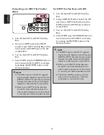
Page 14: ... ANALOG connector at the rear of the HDTV 3 Turn on the the HDTV 4 Select TV using the SOURCE button on the remote side of the HDTV or pressing the TV button on the Remote Control Using the Antenna or Cable for your VCR 1 Turn off the HDTV andVCR 2 Connect the Output to TV RF Out or Antenna Out connector on the rear of yourVCR to the ANTENNA CABLE DIGITAL ANALOG connector at the rear of the HDTV 3...

Page 15: ...ements of the product or consult your cable or satellite operator For HDTV Set Top Boxes with DVI 1 Turn off the HDTV and HDTV Set Top Box 2 Using a HDMI DVI cable connect the DVI end to your HDTV Set Top Box and the HDMI end to the HDMI Input at the rear of the HDTV 3 Turn on the HDTV and HDTV Set Top Box 4 Select HDMI using the SOURCE button on the remote side of the HDTV or directly by pressing...

Page 16: ... and HDTV Set Top Box 7 Select Component using the SOURCE button on the remote side of the HDTV or directly by pressing the COMP button on the Remote Control NOTE Refer to your HDTV Set Top Box user manual for more information about the video output requirements of the product or consult your cable or satellite operator ConnectingYour Basic Set Top Box Using CompositeVideo 1 Turn off the HDTV and ...

Page 17: ...DVD Player Best 1 Turn off the HDTV and DVD player 2 Connect a HDMI cable to the HDMI output of your DVD player and the other end to the HDMI Input at the rear of the HDTV 3 Turn on the HDTV and DVD player 4 Select HDMI using the SOURCE button on the remote side of the HDTV or directly by pressing the HDMI PC button on the Remote Control For DVD Players with DVI 1 Turn off the HDTV and DVD player ...

Page 18: ...onnectors associated with the Component input at the rear of the HDTV 6 Turn on the HDTV and DVD player 7 Select Component using the SOURCE button on the remote side of the HDTV or directly by pressing the COMP button on the Remote Control NOTE Refer to your DVD player user manual for more information about the video output requirements of the product Using S Video AV Connecting your DVD Player Go...

Page 19: ...e Remote Control ConnectingYourVCR orVideo Camera 1 Turn off the HDTV andVCR orVideo Camera 2 Connect the S Video jack on the rear of yourVCR orVideo Camera to the S Video jack in the AV group on the rear of the HDTV 3 Connect an audio cable white and red connectors cable to the audio output connectors associated with the S Video output on yourVCR orVideo Camera and connect the other end to the au...

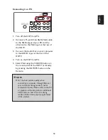
Page 20: ...ut at the rear of the HDTV 4 Turn on the HDTV and PC 5 SelectVGA using the SOURCE button on the remote side of the HDTV or directly by pressing the HDMI PC button on the Remote NOTE For the best picture quality when connecting a computer throughVGA set your computer timing mode to native resolution of panel Please refer to the PC or graphic card s user guide for additional information on how to se...

Page 21: ...annel numbers 6 Channel Labels Show the NTSC ATSC TV channel label menu for user modifying channel labels specifically 7 FAV Channel Setting Show the Favorite Channel List User can edit add delete the favorite channels VIDEO MENU TheVideo menu in most source modes shows as below It provides several video adjustment items for user fine tuning the video display Only inVGA source mode theVideo menu s...

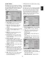
Page 22: ...o output signals and earphone output signals will not be turned off even though the TV speaker is off The default setting is On 9 AVL Choose On or off to adjust volume to be consistent across programs and channels automatically 10 Preset Restore the default audio settings FEATURE MENU The Feature menu in TV mode shows as below This menu gives users the most flexibilities to satisfy their generally...

Page 23: ...on is working The inhibitive channels or source signals can be un lock through pressing theV CHIP key on the remote control and then key in the correct password Note This feature is only available in TV Composite and S Video source modes The default password is 0 0 0 0 Enter Password Parental Control Video Button Lock Block Unrated TV USA Parental Locks Open V Chip Canadian Parental Locks Move Sel...

Page 24: ... Flashing Transparent Translucent Edge Effect Automatic None Raised Depressed Uniform Left Shadow Right Shadow Edge Color Automatic Red Green Blue Yellow Magenta Cyan Black White 11 Input Labels User can edit the input labels 12 Component Setting This option only shows and is available in component mode which provides fine tuning component display Phase Adjust Picture Phase to reduce Horizontal Li...

Page 25: ... These limits are designed to provide reasonable protection against harmful interference in a residential installation This equipment generates uses and can radiate radio frequency energy and if not installed and used in accordance with the instructions may cause harmful interference to radio communications However there is no guarantee that interference will not occur in a particular installation...

Page 26: ...ideo Video Audio Input S VIDEO INPUT Y 1V p p 75 ohm negative sync C 0 286V p p burst signal 75 ohm VIDEO AUDIO INPUT VIDEO 1V p p 75 ohm negative sync AUDIO 300mv rms Component INPUT Rear Component x1 Y 1V p p 75 ohm including sync Pr Cr 0 35V p p 75 ohm Pb Cb 0 35V p p 75 ohm AUDIO 300mv rms Supported resolutions 1080i 720p 480p 480i HDMITerminals HDMI INPUT Rear HDMI x1 HDCP compliant E EDID co...

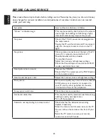
Page 27: ... trouble Try another channel Adjust the contrast and brightness settings Check the Closed Captions control Some TEXT modes could block the screen Good picture but no sound Increase theVOLUME Check if the TV is muted press the MUTE button on the remote control Good sound but poor color Adjust the contrast color and brightness settings Poor picture Poor picture quality may occur when an activated S ...

Page 28: ...ation of America MultichannelTelevision sound MTS The broadcasting standard which allows stereo sounds to be transmitted with theTV picture RF Radio Frequency or modulated signal design used as the carrier for television broadcasts Second Audio Program SAP Another or additional audio channel provided for in the Multichannel Television Sound MTS broadcast standard A monaural soundtrack included wit...

Page 29: ...English English 27 English English ...

Reviews: