background image


50 

Regulation 

FCC Notice 


FCC Class B Radio Frequency Interference Statement WARNING: (FOR FCC CERTIFIED MODELS) 

 
NOTE: This equipment has been tested and found to comply with the limits for a Class B digital device, pursuant to 
Part 15 of the FCC Rules. These limits are designed to provide reasonable protection against harmful interference 
in a residential installation. This equipment generates, uses and can radiate radio frequency energy, and if not 
installed and used in accordance with the instructions, may cause harmful interference to radio communications. 
However, there is no guarantee that interference will not occur in a particular installation. If this equipment does 
cause harmful interference to radio or television reception, which can be determined by turning the equipment off 
and on, the user is encouraged to try to correct the interference by one or more of the following measures: 
 
Reorient or relocate the receiving antenna.   
Increase the separation between the equipment and receiver.   
Connect the equipment into an outlet on a circuit different from that to which the receiver is connected.   
Consult the dealer or an experienced radio/TV technician for help.   


NOTICE : 

 
The changes or modifications not expressly approved by the party responsible for compliance could void the user's 
authority to operate the equipment.   
Shielded interface cables and AC power cord, if any, must be used in order to comply with the emission limits.   
The manufacturer is not responsible for any radio or TV interference caused by unauthorized modification to this 
equipment. It is the responsibilities of the user to correct such interference. It is the responsibility of the user to 
correct such interference.

Summary of Contents for G2460PG

Page 1: ...s...

Page 2: ...8 18 Hotkeys 20 OSD Setting 21 Luminance 3D function disable 22 Luminance 3D function enable 22 Color Setup 24 OSD Setup 26 Extra 28 LED Indicator 30 Driver 31 Monitor Driver 31 Windows 8 31 Windows 7...

Page 3: ...used as follows NOTE A NOTE indicates important information that helps you make better use of your computer system CAUTION A CAUTION indicates either potential damage to hardware or loss of data and...

Page 4: ...purpose of the grounded plug Unplug the unit during a lightning storm or when it will not be used for long periods of time This will protect the monitor from damage due to power surges Do not overload...

Page 5: ...n should be moved with care Never push any object into the slot on the monitor cabinet It could damage circuit parts causing a fire or electric shock Never spill liquids on the monitor Do not place th...

Page 6: ...t the stain instead of strong detergent which will cauterize the product cabinet When cleaning make sure no detergent is leaked into the product The cleaning cloth should not be too rough as it will s...

Page 7: ...plug IMMEDIATELY and contact a Service Center Make sure that the ventilating openings are not blocked by a table or curtain Do not engage the LCD monitor in severe vibration or high impact conditions...

Page 8: ...CD Manual Stand Wire holder Power Cable USB Cable DP Not all signal cables Audio Analog DVI DP USB and HDMI cables will be provided for all countries and regions Please check with the local dealer or...

Page 9: ...9 Setup Stand Base Please setup or remove the base following the steps as below Setup Remove...

Page 10: ...or then adjust the monitor s angle to your own preference Hold the stand so you will not topple the monitor when you change the monitor s angle You are able to adjust the monitor s angle from 5 to 20...

Page 11: ...D monitor before connecting 1 Connect the power cable to the AC port on the back of the monitor 2 Connect one end of the DP cable to the back of the monitor and connect the other end to the computer s...

Page 12: ...visit www nvidia com G sync Driver GeForce 331 58 or higer OS Windows 7 8 8 1 2 3D function The G Sync monitor is NVIDIA 3D Vision Ready monitor To enable 3D function NVIDIA 3D version kit is required...

Page 13: ...ble the wall mounting arm 3 Place the wall mounting arm onto the back of the monitor Line up the holes of the arm with the holes in the back of the monitor 4 Insert the 4 screws into the holes and tig...

Page 14: ...14 Adjusting Setting Optimal Resolution Windows Vista For Windows Vista 1 Click START 2 Click CONTROL PANEL 3 Click Appearance and Personalization 4 Click Personalization...

Page 15: ...15 5 Click Display Settings 6 Set the resolution SLIDE BAR to Optimal preset resolution...

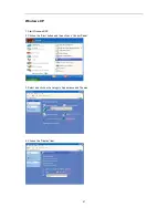
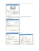
Page 16: ...16 Windows XP For Windows XP 1 Click START 2 Click SETTINGS 3 Click CONTROL PANEL 4 Click Appearance and Themes 5 Double click DISPLAY...

Page 17: ...lution SLIDE BAR to Optimal preset resolution Windows ME 2000 For Windows ME 2000 1 Click START 2 Click SETTINGS 3 Click CONTROL PANEL 4 Double click DISPLAY 5 Click SETTINGS 6 Set the resolution SLID...

Page 18: ...18 Windows 8 For Windows 8 1 Right click and click All apps at the bottom right of the screen 2 Set the View by to Category 3 Click Appearance and Personalization...

Page 19: ...19 4 Click DISPLAY 5 Set the resolution SLIDE BAR to 1920x1080...

Page 20: ...bar Press or button to active ULMB mode NVIDIA ULMB is a technology that eliminates virtually all motion blur associated with LCD displays When playing a game using ULMB moving images will be perfectl...

Page 21: ...functions Once the desired function is highlighted press the MENU button to activate it press or to navigate through the sub menu functions Once the desired function is highlighted press MENU button t...

Page 22: ...1 Press Menu to display menu 2 Press or to select Luminance and press to enter 3 Press or to select submenu and press to enter 4 Press or to adjust 5 Press to exit Contrast 50 Gamma Gamma 1 Overdrive...

Page 23: ...will increase decrease value by 1 Contrast Value 50 Gamma Gamma Adjustment Gamma1 2 2 Gamma2 2 0 Gamma3 2 4 Recall Gamma1 Value Overdrive adjust the response time Strong Medium Light Weak Off Note Whe...

Page 24: ...it Color Setup Color Temp Warm 6500K Recall Warm Color Temperature from EEPROM N A The Color Temperature will be set to Warm Normal 7300K Recall Normal Color Temperature from EEPROM N A Cool 9300K Rec...

Page 25: ...l increase decrease value by 1 Green N A Green gain from Digital register 0 100 Each step will increase decrease value by 1 Blue N A Blue gain from Digital register 0 100 Each step will increase decre...

Page 26: ...to enter 4 Press or to adjust 5 Press to exit OSD Setup Language Set OSD display language to English English is default setting English No need to recall language while press RESET If customer have di...

Page 27: ...p will increase decrease value by 25 0 100 Recall 25 Value Break Reminder Break Reminder if the user continuely work for mare than 1 hurs ON OFF Recall OFF Value Note 1 If turn on a time break reminde...

Page 28: ...28 Extra 1 Press Menu to display menu 2 Press or to select Extra and press to enter 3 Press or to select submenu and press to enter 4 Press or to adjust 5 Press to exit...

Page 29: ...cute reset return to main menu NO ULMB G_sync function disable and timing V freq 85hz On Off G_sync function enable or display card do not support G_sync function Off Note 1 The OSD language is not be...

Page 30: ...30 LED Indicator Status LED Color Full Power Mode Green or Blue Active off Mode Orange or red...

Page 31: ...1 Driver Monitor Driver Windows 8 1 Start Windows 8 2 Right click and click All apps at the bottom right of the screen 3 Click on the Control panel icon 4 Set the View by to Large icons or Small icons...

Page 32: ...32 5 Click on the Display icon 6 Click on the Change display settings button 7 Click the Advanced Settings button...

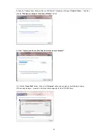
Page 33: ...r tab and then click the Properties button 9 Click the Driver tab 10 Open the Update Driver Software Generic PnP Monitor window by clicking on Update Driver and then click the Browse my computer for d...

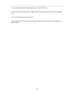
Page 34: ...drive letter designator for the CD ROM drive 13 Select the xxx inf file and click the Open button Click the OK button 14 Select your monitor model and click the Next button The files will be copied fr...

Page 35: ...35 Windows 7 1 Start Windows 7 2 Click on the Start button and then click on Control Panel 3 Click on the Display icon 4 Ckick on the Change display settings button...

Page 36: ...36 5 Click the Advanced Settings button 6 Click the Monitor tab and then click the Properties button 7 Click the Driver tab...

Page 37: ...click the Browse my computer for driver software button 9 Select Let me pick from a list of device drivers on my computer 10 Click the Have Disk button Click on the Browse button and navigate to the...

Page 38: ...lect your monitor model and click the Next button The files will be copied from the CD to your hard disk drive 13 Close all open windows and remove the CD 14 Restart the system The system will automat...

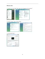
Page 39: ...39 Windows Vista 1 Click Start and Control Panel Then double click on Appearance and Personalization 2 Click Personalization and then Display Settings 3 Click Advanced Settings...

Page 40: ...w click Continue 5 Click Update Driver in the Driver tab 6 Check the Browse my computer for driver software checkbox and click Let me pick from a list of device drivers on my computer 7 Click on the H...

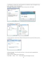
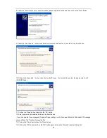
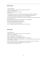
Page 41: ...41 Windows XP 1 Start Windows XP 2 Click on the Start button and then click on Control Panel 3 Select and click on the category Appearance and Themes 4 Click on the Display Item...

Page 42: ...nitor tab If the Properties button is inactive it means your monitor is properly configured Please stop installation If the Properties button is active click on Properties button Please follow the ste...

Page 43: ...se button and then select the appropriate drive F CD ROM Drive 11 Click on the Open button then click the OK button 12 Select your monitor model and click on the Next button If you can see the has not...

Page 44: ...e Open button then click on the OK button 10 Select your monitor model and click on the Next button 11 Click on the Finish button then the Close button If you can see the Digital Signature Not Found w...

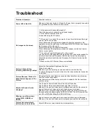
Page 45: ...icture Is Fuzzy Has Ghosting Shadowing Problem Adjust the Contrast and Brightness Controls Press to auto adjust Make sure you are not using an extension cable or switch box We recommend plugging the m...

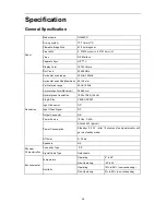
Page 46: ...0Hz 150Hz Vertical scan Size Maximum 298 89 mm Optimal preset resolution 1920 x 1080 144Hz Plug Play VESA DDC2B Input Connector DP Input Video Signal DP Output Connector NA Power Source 19Vdc 3 42A Po...

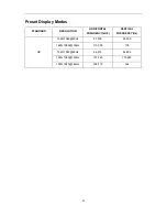
Page 47: ...des STANDARD RESOLUTION HORIZONTAL FREQUENCY kHZ VERTICAL FREQUENCY Hz HD 1920 1080 60Hz 67 500 60 000 1920 1080 100Hz 113 300 100 1920 1080 85Hz 96 513 84 884 1920 1080 120Hz 137 260 119 982 1920 108...

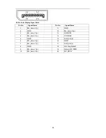
Page 48: ...Pin No Signal Name 1 ML_Lane 3 n 11 GND 2 GND 12 ML_Lane 0 p 3 ML_Lane 3 p 13 CONFIG1 4 ML_Lane 2 n 14 CONFIG2 5 GND 15 AUX_CH p 6 ML_Lane 2 p 16 GND 7 ML_Lane 1 n 17 AUX_CH n 8 GND 18 Hot Plug Detect...

Page 49: ...itor is equipped with VESA DDC2B capabilities according to the VESA DDC STANDARD It allows the monitor to inform the host system of its identity and depending on the level of DDC used communicate addi...

Page 50: ...e determined by turning the equipment off and on the user is encouraged to try to correct the interference by one or more of the following measures Reorient or relocate the receiving antenna Increase...

Page 51: ...ere you can drop off your waste equipment for recycling please contact your local city office your household waste disposal service or the shop where you purchased the product This symbol on the produ...

Page 52: ...ox to protects your monitor well enough during transport Put the RMA number on the address label Put the RMA number on the shipping carton AOC International Europe B V is not responsible for any damag...

Page 53: ...NAL EUROPE B V LIABILITY WHETHER BASED ON CONTRACT TORT WARRANTY STRICT LIABILITY OR OTHER THEORY SHALL NOT EXCEED THE PRICE OF THE INDIVIDUAL UNIT WHOSE DEFECT OR DAMAGE IS THE BASIS OF THE CLAIM IN...

Page 54: ...mage during shipment Pay all shipping charges EPI is not responsible for damage to inbound product that was not properly packaged EPI will pay the return shipment charges within one of the countries s...

Page 55: ...DAMAGES SO THE ABOVE LIMITATION MAY NOT APPLY TO YOU ALTHOUGH THIS LIMITED WARRANTY GIVES YOU SPECIFIC LEGAL RIGHTS YOU MAY HAVE OTHER RIGHTS WHICH MAY VARY FROM STATE TO STATE In the United States of...

Reviews: