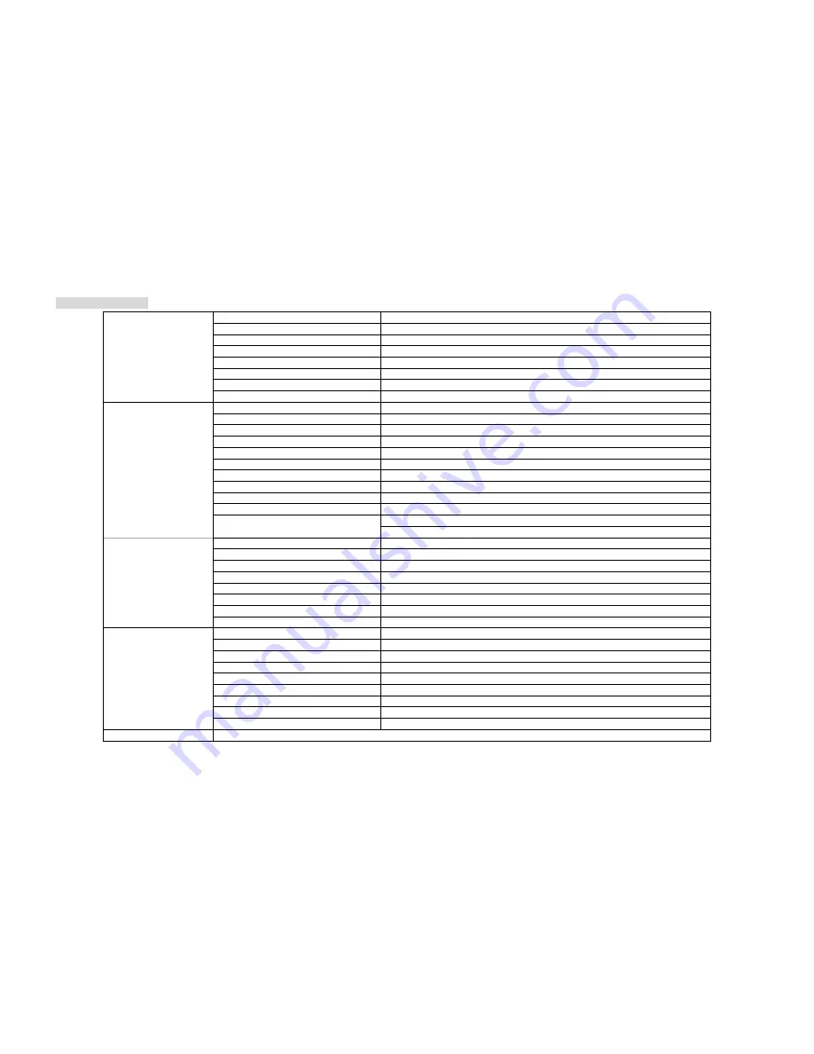
AOC 210V User Manual Download Page 16

Product Information 

Model number   

210V

Driving system   

TFT Color LCD   

Size   

558mm ( 22")   

Pixel pitch   

0.282mm(H) x0.282 mm(V)   

Video   

R, G, B Analog lnterface & Digital Interface   

Separate Sync.   

H/V TTL    

Display Color   

16.7 million Colors   

LCD Panel   

Dot Clock   

165MHz   

Horizontal scan range   

30 kHz - 83 KHz   

Horizontal scan Size(Maximum)   

473mm

Vertical scan range   

55 Hz - 75 Hz   

Vertical scan Size(Maximum)   

296mm

Optimal preset resolution   

1680 x 1050 (60 Hz)   

Highest preset resolution   

1680 x 1050 (60 Hz)   

Plug & Play   

VESA DDC2B/CI 

Input Connector   

D-Sub 15pin & DVI-D   

Input Video Signal   

Analog: 0.7Vp-p(standard), 75 OHM, Positive & DVI-D Digital Interface (TMDS)   

Power Source   

100~240VAC, 47~63Hz   
Active < 49W   

Resolution   

Power Consumption   

Standby < 1W   

Connector Type   

15-pin Mini D-Sub & DVI-D   

Signal Cable Type   

Detachable   

Dimensions & Weight:   


Height (with base)

408.39mm 

Width   

507.20mm 

Depth

194.86mm 

Weight (monitor only)   

5.81kg

Physical Characteristics   

Weight (with packaging)   

7.85kg

Temperature:   
Operating   

0°- +50° 

Non-Operating   

-20° - 60° 

Humidity:   


Operating   

10% to 85% (non-condensing)   

Non-Operating   

5% to 80% (non-condensing)   

Altitude:   


Operating   

0~ 3000m (0~ 10000 ft )   

Environmental   

Non-Operating   

0~ 5000m (0~ 15000 ft )   

Regulations   

CCC/cUL/FCC/CE/TCO03/RoHS 

Summary of Contents for 210V

Page 1: ...a and New Zealand National Conventions The following subsections describe notational conventions used in this document Notes Cautions and Warnings Throughout this guide blocks of text may be accompani...

Page 2: ...ing the equipment off and on the user is encouraged to try to correct the interference by one or more of the following measures 1 Reorient or relocate the receiving antenna 2 Increase the separation b...

Page 3: ...n may result in exposure to shock electrical hazards and or mechanical hazards Read and follow these precautions when connecting and using your computer monitor PRECAUTIONS x Do not use the monitor ne...

Page 4: ...ords Overloading can result in fire or electric shock x Never push any object into the slot on the monitor cabinet It could short circuit parts causing a fire or electric shock Never spill liquids on...

Page 5: ...ded to look at the full face of the monitor then adjust the monitor s angle to your own preference x Hold the stand so you do not topple the monitor when you change the monitor s angle x You are able...

Page 6: ...t one end of the 15 pin D Sub cable to the back of the monitor and connect the other end to the computer s D Sub port 3 Optional Requires a video card with DVI port Connect one end of the 24 pin DVI c...

Page 7: ...1 Remove the base 2 Follow the manufacturer s instructions to assemble the wall mounting arm 3 Place the wall mounting arm onto the back of the monitor Line up the holes of the arm with the holes in t...

Page 8: ...uble click DISPLAY 5 Click SETTINGS 6 Set the resolution SLIDE BAR to 1680 by 1050 External Controls Press the power button to turn the monitor on or off The other control knobs are located at front p...

Page 9: ...through the sub menu functions Once the desired function is highlighted press MENU button to activate it x Press or to change the settings of the selected function To exit and save select the exit fu...

Page 10: ...co mode Sports Sports Mode Gamma1 Adjust to Gamma1 Gamma2 Adjust to Gamma 2 Gamma Gamma3 Adjust to Gamma 3 Off Disable dynamic contrast ratio DCR On Enable dynamic contrast ratio Image Setup Clock 0 1...

Page 11: ...r Enable AutoDetect Mode Demo on or off Disable or Enable Demo Picture Boost Frame Size 0 100 Adjust Frame Size Brightness 0 100 Adjust Frame Brightness Contrast 0 100 Adjust Frame Contrast Hue 0 100...

Page 12: ...LED Indicators Status LED Color Full Power Mode Green Active off Mode Orange...

Page 13: ...ck on PROPERTIES 2 Click the SETTINGS tab and then click ADVANCED 3 Click the MONITOR tab and then click PROPERTIES 4 Under MONITOR PROPERTIES click DRIVER then click UPDATE DRIVER 5 On the HARDWARE U...

Page 14: ...or Click Browse my computer for driver software 9 Select Let me pick from a list of device drivers on my computer 10 Click Have Disk Click Browse Select driver file on the disk D Drivers model name wh...

Page 15: ...ar away from the monitor as possible x Use the maximum refresh rate your monitor is capable of at the resolution your are using Monitor Is Stuck In Active Off Mode x The Computer Power Switch should b...

Page 16: ...DC2B CI Input Connector D Sub 15pin DVI D Input Video Signal Analog 0 7Vp p standard 75 OHM Positive DVI D Digital Interface TMDS Power Source 100 240VAC 47 63Hz Active 49W Resolution Power Consumptio...

Page 17: ...STAND RESOLUTION HORIZONTAL FREQUENCY kHZ VERTICAL FREQUENCY Hz Dos mode 720 x 400 31 47 70 0 VGA 640 x 480 31 47 60 0 VGA 640 x 480 37 50 75 0 SVGA 800 x 600 37 879 60 0 SVGA 800 x 600 46 875 75 0 X...

Page 18: ...nts Pin Number 15 Pin Side of the Signal Cable 1 Video Red 2 Video Green 3 Video Blue 4 N C 5 Ground 6 GND R 7 GND G 8 GND B 9 5V 10 Detect Cable 11 N C 12 DDC Serial data 13 H sync 14 V sync 15 DDC S...

Page 19: ...2 TMDS Clock Shield 7 DDC Data 15 Ground for 5V 23 TMDS Clock 8 N C 16 Hot Plug Detect 24 TMDS Clock Plug and Play Plug Play DDC2B Feature This monitor is equipped with VESA DDC2B capabilities accordi...

Reviews: