


[SET ON setting]
[SET OFF setting]
[Automatic setting]
Perform settings while no object
to be detected exists.
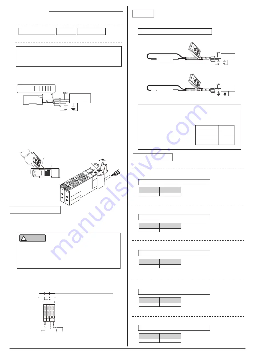
Work
Black: DN
Red: DP
AnyWireASLINK
Master
Green:
24V
White: 0V
Black: DN
Red: DP
AnyWireASLINK
Master
Green:
24V
White: 0V
Hysteresis
Alarm value Hi
Alarm value Lo
5%
Threshold
50%
80%
20%
Perform settings while any object
to be detected exists.
Default: 50 (AD value)
If the display setting for the light receiving level is the AD value
display (parameter 08), then "threshold," "hysteresis," "alarm
value Hi," and "alarm value Lo" are automatically set to the
following percentages based on the difference in the AD
values between when a work is
present and when a work is
absent stored during teaching
operation.
Input
AnyWire address
Setting address
0
255
1
2
3
Example) Addresses with four fiber amplifiers connected
“0” “1” “2” “3”
[Various settings]
Open the protective cover
during settings
Setting port
■
Common procedure for address writer operation
■
Item
Transmission
signal
* Make sure to use a 24V DC stabilized power supply for the power supply to be connected.
Address number setting
Teaching
Parameter setting
ASLINKAMP
Fig. 1
Setting port
LINK
IN
ALM
Emitter
Black: DN
Red: DP
AnyWireASLINK
Master
Green:
24V
White: 0V
24V DC*
Address number setting
Parameter setting
-L*F1011 7/11-
Teaching
■
Change of threshold
AD value
0 - 4095
- Address writer (ARW-04): Parameter 01
0 - 100%
■
Change of hysteresis
0 - 4095
Default: 5 (AD value)
- Address writer (ARW-04): Parameter 02
0 - 100%
■
Alarm value Hi setting
■
Alarm value Lo setting
0 - 4095
Default: 0 (AD value)
- Address writer (ARW-04): Parameter 03
0 - 100%
0 - 4095
Default: 0 (AD value)
- Address writer (ARW-04): Parameter 04
0 - 100%
Set a monitor time for the alarm judgment value.
Variable
3 - 255
Default: 50
- Address writer (ARW-04): Parameter 05
100ms
Unit
■
Alarm value monitor time setting
Carry out setting with the work actually used.
0 - 100%
AD value
0 - 100%
AD value
0 - 100%
AD value
0 - 100%
* Setting scope depends on the setting of parameter 8.
Be sure to connect to the AnyWireASLINK master unit to use.
Setting requires the address writer ARW-04 (Ver.04-1.01 or higher).
For details about the operation method, refer to the address
writer's Products Guide.
Store the status when a work is present and when a work is absent in the
ASLINKAMP.
1. Connect the terminal to the AnyWireASLINK master unit.
Set with the address writer while supplying transmission signal (DP/DN)
and power supply (24V/0V).
2. Setting is required for all terminals.
Open the protective cover of the terminal to be set, and direct the address
writer toward the setting port as shown in Fig. 1 to perform settings
(Bring the emitter as close as possible to the setting port.)
Close the protective cover of terminals that are not to be set.
The address number is used to set which number of the
transmission frame to start with for the terminal to occupy.
Set the address number in a range from "0" to "254."
CAUTION
!
The default address-number setting of the terminal is "255," which
means no setting.
If the address number setting is "255," the terminal cannot perform
input/output operations.
Make sure to use the terminal after setting the address number within
the range of "0 to 254."
Set the threshold of the light receiving level to judge the presence/absence of
detection.
* Difference in the detection state stored in teaching is 100%.
Set the amount of change in the light receiving value required to turn the
detection state from ON to OFF.
Set an upper limit for the alarm judgment value.
* Set the alarm values so that Hi is greater than Lo.
Set a lower limit for the alarm judgment value.
* Set the alarm values so that Hi is greater than Lo.


