


Configuration
14 (30)
4.3
Wireless Settings
4.3.1
Wireless Settings
AP
Access Point mode. The unit will act as a central connection point which other wireless
clients can connect to. This is the default mode.
AP-Client
Provides one-to-many MAC address mapping so that multiple stations behind the AP
can transparently connect to the other AP even if they do not support WDS.
Client
The unit will function as a wireless client to connect your wired devices to a wireless
network. This mode provides no access point services but supports 802.1X.
Bridge
In this mode, the device functions as a bridge between the network on its WAN port and
the devices on its LAN port and those connected to it wirelessly.
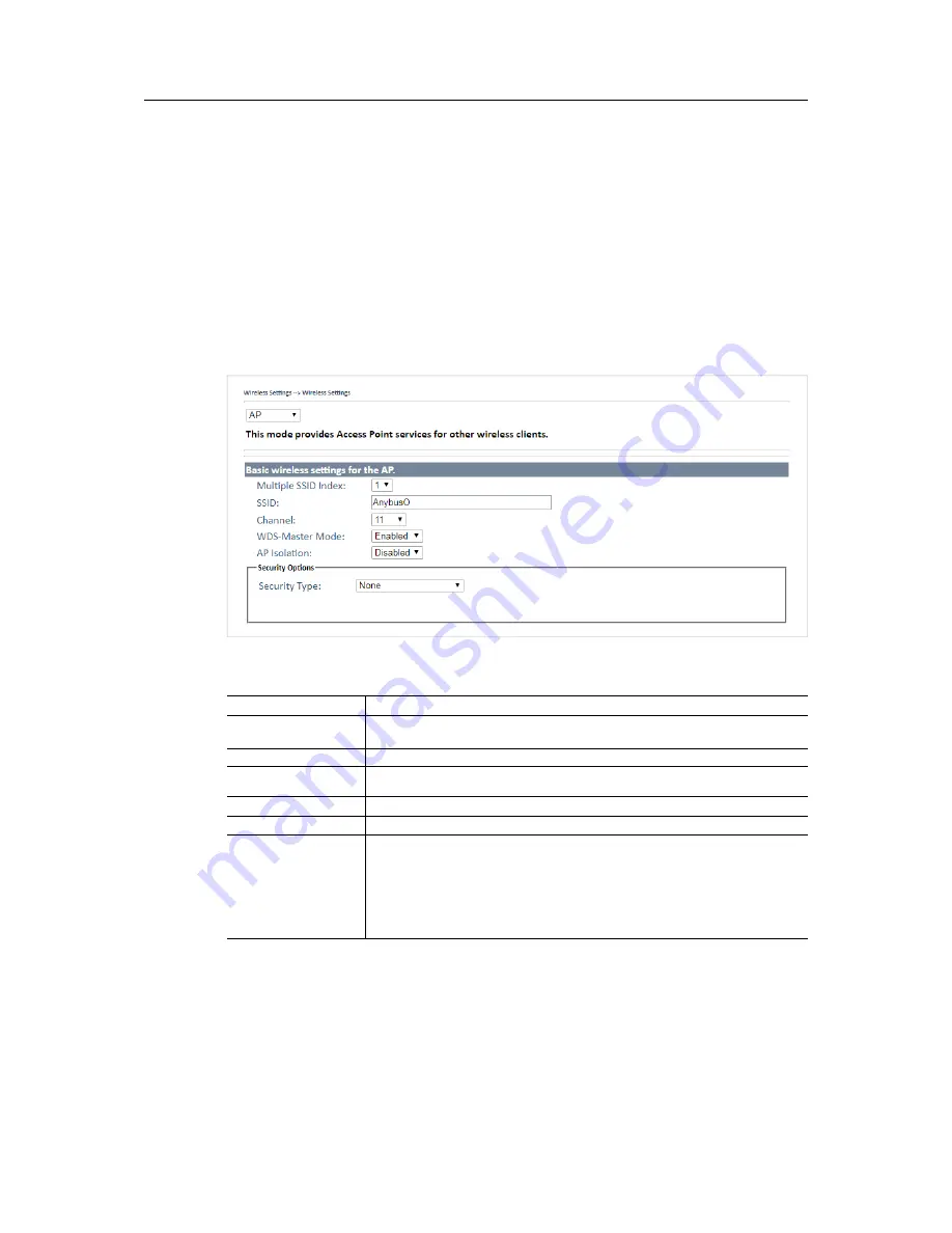
Wireless settings – AP
Fig. 15
Wireless settings – AP
AP Settings
Label
Description
Multiple SSID index
The device supports multiple SSIDs (network names) which are indexed 1 to 4.
This dropdown selects the index of the SSID to configure in the following settings.
SSID
Enter an SSID for the network.
Channel
Select the WLAN channel to use for the access point. This channel will be used for
all 4 SSIDs.
WDS-Master Mode
When enabled, the unit will act as a WDS master on this network.
AP Isolation
Prevents clients connected to the AP from communicating directly with each other.
Security options
None
: no encryption
WEP
: WEP (Wired Equivalent Privacy)
WPA/WPA2 Personal
: uses a pre-shared key for authentication that is shared
between the AP and all clients.
802.1x
: authentication through a RADIUS server.
WPA/WPA2 Enterprise
: WPA/WPA2 Personal plus 802.1x RADIUS authentication.
See also
RADIUS Authentication, p. 16
.
Anybus
®
WLAN Access Point IP67 User Manual
SCM-1202-094-EN 1.0


