Copyright All Rights Reserved. P-MU-ML-600 Published: 2020.11.25
ML-600M
275
25
24
203
43.5
83.5
3
116
250
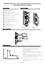
ML-600 Electric Lock (with Mechanical Override)
Installation Instructions
Specifications
Dimensions
Wiring Diagram
Lock Mode: Fail-Secure
Operating Voltage: 12~24VAC/DC
Current Draw: 500mA / 12VDC, 250mA / 24VDC
Operating Temperature: -10°C~+49°C
Humidity: 0~85% non-condensing
Preload: 300 lbs of pressure strength
Solenoid Testing: Tested up to 250,000 cycles
Latch Throw: 16mm
Relock Delay Time: 3 seconds
Optional Cylinder: EYC-72
Unti:mm
ML-600M
28
100
150
125
2
Lock Body
White
White
N.C.
COM
N.O.
Access Control
(N.O. + COM.)
Power
Supply
Black
Red
Yellow
Green
Blue
Door Status Output
Circuit Description
Strike Plates
Currrent Draw
Pull in (2 secs)
Holding
Energy-saving
Door closed (3 secs)
De-energized
Time (seconds)
De-engergized
A. De-energized: Door is in locked status.(Operating in fail-secure mode)
B. Pull-in:The electric lock is energized through access control devices.
(Please refer to the wiring diagram)
C. Energy-saving: After supplying power to unlock for 2 seconds , the current
draw will drop to save energy. During this time, the electric lock remains unlocked.
D. Door closed:
After door is closed, the NIB (deadlatch) will will retract into the lock housing
and press the internal micro switch. After door keeps closing for 3 seconds, the lock
will be completely de-energized and the door will remain locked.
(Without keeping door closed for 3 seconds, the electric lock will not be de-energized
and remains unlocked.)
30 Backset
Trigger to unlock
12~24VDC/AC


