3 Installation
C58IB004EN-D
17
The connector for temperature measurement and
the connector for heating are located in the connec-
tion device for gas/vacuum and temperature control,
described in chapter 2.2.4 Connection Device.
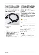
The instrument is delivered together with two cables
for the connection of DHS 1100 to CCU 100. At one
end of the cables a cable fixation (1) is mounted.
This side is connected to CCU 100.
Fig. 9: Connection cables
1
Cable fixation
2
Temperature sensor cable
3
Heater cable
Connect the electrical cables to the connection de-
vice as follows:
1. Feed the cables through the appropriate port of
the diffractometer cabinet as described in the
diffractometer instruction manual.
2. Connect the heater cable to the connection
device of DHS 1100.
3. Connect the temperature sensor cable to the
connection device of DHS 1100. The tempera-
ture sensor cable contains the wires for the type
S thermocouple, measuring the sample tem-
perature inside the DHS 1100, and the wires for
the thermoswitch which protects the DHS 1100
housing from being overheated.
Connect the electrical cables to the CCU 100 rear
panel as follows:
1. Connect the side with the cable holder to the
connector sensors/heater on the rear panel of
CCU 100 (see Fig. 7).
2. Make sure the mains switch on CCU 100 is OFF
and connect the mains power cable to the
POWER connector.
3.7 Connecting CCU 100 with a Com-
puter
The RS 232 serial port at the rear panel of CCU 100
allows you to connect the CCU 100 to a computer
for remote control (see Fig. 7(4)).
A null modem RS 232 cable is required to connect
the CCU 100 to a PC.
1
2
3
WARNING
Risk of damage
This instrument must be connected to protective
ground.
NOTICE
According to EN60950 standards, the RS 232
serial interface represents a SELV circuit which
must therefore only be connected to SELV cir-
cuits.


