Antech AN-350 Operation Manual Download Page 27


OPERATION MANUAL FOR SCD( AN-350) SERIES CAPACITOR DISCHARGE STUD WELDING MACHINES 

10/2000                                                                          ANTECH ELECT.LTD. 

26

 
9.  Diagnostics and Repairing:  


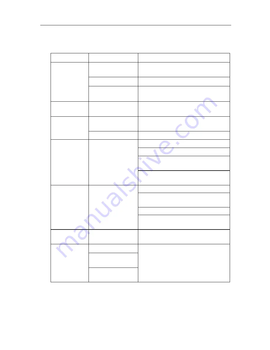
The following table provides a guide for troubleshooting the welding machine: 

Symptom 

Cause 

Solution 

Faulty input  power 

Check supply voltage if it is 220V
± 15%? 50/60Hz 

Loose power plug   Connect the power socket 

‘ POWER’ LED 
does not turn 
on 

Loosen or broken 
power wires  

Open the power plug and re-connect the 
power wires 


Faulty controller  Replace defective AN350 controller 

AN-350/SCR driver  
wires open-circuit 

Check wiring between AN350 and the SCR 
driver, ensure good connections 

AN-350 shows 
E01 error 

SCR over-heated 

Check SCR and associated assembly 

Check discharge SCR assembly 

Replace faulty SCR (thyrister) 

Check  X5-5 ? X5-6 on SCR driver for 
wirings to discharge SCR 

AN-350 shows 
E03 error 

Discharge fault 

Replace faulty AN-350 controller or 
SCR driver board 

Check charging SCR assembly 
Check  X6-2 , X6-3 on SCR driver for 
wirings to the charging SCR 

Replace charging SCR or resistor 

AN-350 shows 
E04 error 

Charging fault 

Replace faulty AN-350 controller or 
SCR driver board 

AN-350 shows 
E05 error 

Over-voltage fault 

Replace faulty AN-350 controller or 
SCR driver board 

Broken control wire 

Faulty stun gun 
solenoid 

Malfunction 
Stud Gun 

Faulty mechanical 
parts 

Inspect wiring and/or replace stun 
gun assembly 

 Note: 1. The power must be disconnected for diagnostics and repairing in 

order to prevent accidents!  

2.Contact our technical service department immediately for 

technical advice, service, repairing and spare parts. 

Summary of Contents for AN-350

Page 1: ...ANUAL FOR THE SCD SERIES CAPACITOR DISCHARGE STUD WELDING MACHINE SERIES SCD MODEL AN 350 SERIAL AE0 DATE ANTECH ELECTRONICS LTD 030 056 01 001 Please read this manual carefully before using this weld...

Page 2: ...t developed by Antech Electronics Ltd It is built with a dedicated AN 350 controller that provides stable outputs regardless of any input voltage and temperature changes The internal memory supports t...

Page 3: ...ot operate the welding machine if the chassis is open 5 Any service repairing and maintenance should only be performed by qualified technicians Be cautious when dealing with high voltage components su...

Page 4: ...INDEX 1 Introduction 4 2 Specifications 4 3 Installations 4 4 The Control Unit 7 5 The Stud Welding Gun 14 6 Stud Welding Procedure 23 7 Welding Tips 24 8 Maintenance 25 9 Diagnostics 26 10 Parameter...

Page 5: ...rience and continuous improvements the SCD series of stud welding machines have been developed to meet the requirements of the welding industry It is suitable for the stud welding of stainless steel m...

Page 6: ...g gun systems 1 Connect the pedal push button switch to the connector on the front of the control unit 2 Clean the air hoses and assembly and then connect the air outlet from the air compressor to the...

Page 7: ...tighten the connection with the mounting ring of the plug 3 2 3 Connect the earth cables to the earth fast on connector on the front panel Turn clockwise to tighten the connection properly 3 2 4 Conne...

Page 8: ...ng 3 series of program welding parameters Overheat indication Discharge thyrister diagnostics Open circuited Short circuited indication Capacitor over voltage indication and protection Under voltage i...

Page 9: ...itions of the welding system NOTE For 50 Hz line frequency 1 cycle 20 msec 4 3 3 Operating Specifications Input Voltage Single phase 220V 15 50 60Hz automatic frequency detection Solenoid Voltage DC24...

Page 10: ...ection of the welding gun 4 4 5 4 pins Socket Used for the connection of the control wires of the welding gun 4 4 6 Input Power port 4 4 7 Fast on Socket Used for the connection of the Welding gun cab...

Page 11: ...arged to the preset value and it is ready for welding 4 5 4 Solenoid Indicator VALVE This LED indicator lights up when the solenoid is energized valid only if the welding gun is driven by solenoid 4 5...

Page 12: ...P3 XX P5 XXX P8 XXXX P9 XXXX 4 5 8 Clear Button C Press the Clear button to exit from any display mode to the rdy mode 4 5 9 Increment Button Press this button once would increase the display value by...

Page 13: ...resistor P5 Delay between charging discharging P6 Solenoid starting time P7 Discharge delay time P8 Software version P9 DIP switch positions P10 Input line voltage P11 Current Capacitor voltage P12 C...

Page 14: ...value and it will be saved to the internal memory of the controller The display will show the next parameter on the list Repeat step 4 to change the value of the parameter if necessary until all para...

Page 15: ...rrent is made at the moment after the stud is pulled away from the work piece with a gap maintained between them as shown in Figure 6 Diagram 6 Gap Method Stud Welding Procedure Gap method stud weldin...

Page 16: ...ial and size of studs there are three different stud welding guns available for selection Stud Gun Descriptions Model ESP 9 Type Gap method Suitable for Mild steel Stainless Steel Aluminum etc Diamete...

Page 17: ...etc Length of Gun cable 6 meter H 100 Pressure Adjustment method By spring and or stud tip adjustments Model HP TSK310 Type Contact method Suitable for Mild steel Stainless Steel Aluminum etc Diamete...

Page 18: ...ng nut 5 Stud stop s tightening nut 3 Adjustable stud stop 6 Supporting foot 1 Chuck The chuck is used for the holding of the stud nail and for the discharge current to go through its contact with the...

Page 19: ...he stud stop has been fixed it is used to tighten up the stud stop in order to prevent it from shifting 6 Supporting feet The three supporting feet determines a stable surface This helps to maintain a...

Page 20: ...to standard gap which allows a longer welding time and intensifies degassing 3 Turn the chuck to adjust the gap Turn to the right greater gap shorter welding cycle Turn to the left smaller gap longer...

Page 21: ...ighten the chuck and stud stop 2 Selection of Stud stop As shown in Figure 11 Figure 11 Selection of the Length of Stud Stop When selecting the length of Stud stop use the above table and make a selec...

Page 22: ...0 stud welding gun 1 Adjustment of chuck The purpose of adjusting the chuck is for the positioning of stud screw pin a release chuck locking nut in anti clockwise direction b rotate stud stop in anti...

Page 23: ...d if the size or length of the stud nail is changed 4 Do weld tests and inspection after adjustments 5 Inspection of weld tests a Visual Inspection After stud welding check the weld pool between the b...

Page 24: ...diameter of stud nail The capacitor voltage P5 is the main parameter to be setup properly The higher the capacitor voltage the higher is the output welding current and energy 6 2 Stud Welding Practic...

Page 25: ...ged chuck 7 4 Contaminated rusty painted or dusty workpiece surface that might resist the flow of welding current 7 5 Improper selection of welding gun concerning the material and size of the workpiec...

Page 26: ...not set the capacitor voltage to a high level right away Start with a capacitor voltage of 30V and increase by 10V once every minute until 175V Maintain at 175V for one hour before regular stud weldin...

Page 27: ...assembly Check discharge SCR assembly Replace faulty SCR thyrister Check X5 5 X5 6 on SCR driver for wirings to discharge SCR AN 350 shows E03 error Discharge fault Replace faulty AN 350 controller o...

Page 28: ...1 S 2 S 3 S _ S _ S _ PreSqueeze Time P01 Hold Time P03 Capacitor Voltage P05 Weld Counter P08 Preset Counter P09 Descriptions Material Stud Nail Diameter S _ S _ S _ S _ S _ S _ PreSqueeze Time P01...

Reviews: