background image


4.


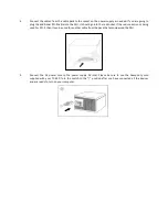
Connect the cables from the cable pack to the socket on the power supply as needed. If you are going to 
plug the additional PCI-E cable into the PSU, it should go into the red socket. If the red socket is not being 
used for PCI-E, then it can be used for another cable from the pack that accompanied the PSU. 


5.


Connect  the  AC  power  cord  to  the  power  supply  AC  inlet.  Please  be  sure  to  use  the  heavy-duty  cord 
supplied  with  your  TP-650.  Turn  the  switch  to  the  “|”  position  after  you  have  connected  all  the  devices 
and are ready to turn on your computer.   


Summary of Contents for TRUEPOWER TP-650

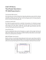
Page 1: ...TRUEPOWER NEW 650 WATT POWER SUPPLY USER S MANUAL ...

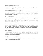
Page 2: ...ive PFC which improves the power factor value of the power supply by altering the input current wave shape which helps power transmission across the grid SYSTEM PROTECTION A variety of industrial grade safety circuitry will help protect your computer OVP Over Voltage Protection SCP Short Circuit Protection and OCP Over Current Protection Sometimes the PSU will latch into a protected shutdown state...

Page 3: ...ther benefit is that transient response time is almost 100 times faster providing remarkably stable power output in response to changing loads PULSE WIDTH MODULATION PWM FAN Pulse Width Modulation technology allows the TruePower New series to finely control the speed of the power supply s fan By using this method instead of the traditional voltage controlled fans this PSU s fan can run up to 50 qu...

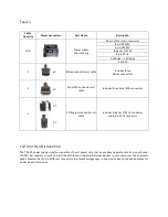
Page 4: ...hree Serial ATA connectors 1 X 1 X 1 PCI Express connectors w cable Includes 8 pin 6 2 PCI E connector and 6 pin PCI E connector 12 VOLT RAIL DISTRIBUTION The TP 650 power supply uses four separate 12 volt power rails Just as you have separate circuits in your house the PSU has separate circuits to aid in the distribution of power between devices in your computer The engineers have allocated the r...

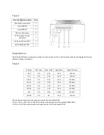
Page 5: ... 0A 22A 3 120 mV 12V3 0A 25A 3 120 mV 12V4 0A 25A 3 120 mV 12V 0A 0 8A 10 120 mV 5VSB 0A 3A 5 50 mV The continuous maximum total output power shall not exceed 650W 12V1 12V2 12V3 and 12V4 DC maximum output power shall not exceed 648W 54A 3 3V and 5V DC maximum combined output power shall not exceed 170W Direct Cabling Connectors Rail 20 4 main connector 1 4 pin ATX12V 2 8 pin EPS12V 2 PCI E w blue...

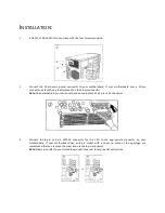
Page 6: ...n connector Note The detachable 4 pin section cannot be used in place of a 4 pin 12V connector 3 Connect the 8 pin or 4 pin ATX12V connector for the CPU to the appropriate connector on your motherboard If your motherboard has an 8 pin socket with a cover on some of the openings we recommend that you remove the cover and use the 8 pin connector Note Please also refer to your motherboard user s manu...

Page 7: ...e red socket If the red socket is not being used for PCI E then it can be used for another cable from the pack that accompanied the PSU 5 Connect the AC power cord to the power supply AC inlet Please be sure to use the heavy duty cord supplied with your TP 650 Turn the switch to the position after you have connected all the devices and are ready to turn on your computer ...

Page 8: ...31 0 10 462 2060 fax 31 0 10 437 1752 Technical Support US Canada 1 800 22ANTEC customersupport antec com Europe 31 0 10 462 2060 europe techsupport antec com www antec com Copyright 2009 Antec Inc All rights reserved All trademarks are the property of their respective owners Reproduction in whole or in part without written permission is prohibited ...

Reviews: