Antec ISK 310-150 User Manual Download Page 7


2.4


I

NTERNAL 

2.5”


D

EVICE 

I

NSTALLATION


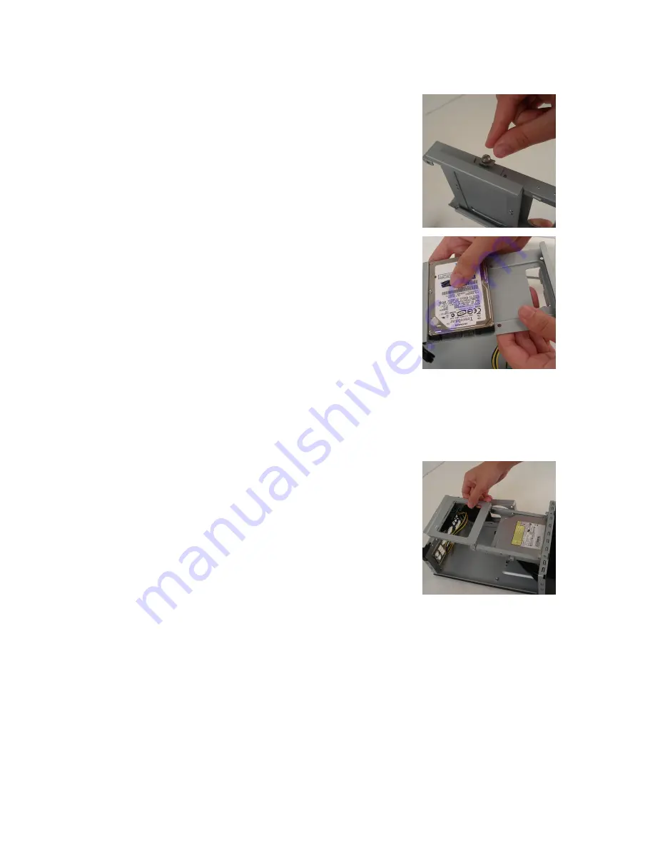
Remove the top panel as described in section 2.1. Included at the top 
of the drive tray assembly is a HDD tray that can support up to two 
2.5” devices. 
 
1.


On the right side of the drive tray assembly, remove the 
thumbscrew holding the HDD tray to the rest of the device.  

2.


Slide the HDD tray back a centimeter so the locking hinges 
unhook. 

3.


Pull the HDD tray away from the drive tray assembly. 

4.


Align your 2.5” device with the HDD tray. Invert the tray so the 
lower screw holes are accessible, and then secure the device to 
the tray with the provided Phillips-head screws. 

5.


Reattach the HDD tray to the drive tray assembly and replace 
the thumbscrew. 

6.


Connect the data and power connectors from the motherboard 
and power supply to the device. 


2.5


E

XTERNAL 

S

LIM 

O

PTICAL 

D

EVICE 

I

NSTALLATION


Remove the top panel and drive tray assembly as described in sections 2.1 and 2.2. There is one 
externally accessible slim optical drive bay that is compatible with a slim optical drive. 
 
1.


While facing the front of the case, press on the upper right of 
the front of the drive bay cover until it clicks, then release to 
allow the cover to unhinge. 

2.


Remove the drive bay face plate by applying pressure to the 
inside of the plate until it pops free of the bezel. 

3.


Install your slim optical drive in the drive bay assembly by 
sliding it into position from the rear of the assembly. Secure the 
device in place by attaching the included small screw on the 
right-hand side of the tray. 

4.


Connect the data and power connectors from the motherboard 
and power adapter to the device. 

5.


Replace the drive tray assembly in the chassis. 


Summary of Contents for ISK 310-150

Page 1: ...ISK 310 150 USER S MANUAL ...

Page 2: ... 2 Removing the Drive Tray Assembly 5 2 3 Motherboard Installation 5 2 4 Internal 2 5 Device Installation 5 2 5 External Slim 5 25 Device Installation 6 CONNECTING THE FRONT I O PORTS 3 1 USB 2 0 Ports 7 3 2 eSATA Port 7 3 3 AC 97 HD Audio Ports 7 3 4 Switch and LED Connectors 8 3 5 Rewiring Motherboard Header Connections 8 COOLING SYSTEM 4 1 TriCool Exhaust Fan 9 ...

Page 3: ...g the motherboard and peripherals please refer to the user s manuals that come with those components Although care has been taken to prevent sharp edges in your Antec case we strongly recommend taking the appropriate time and care when working with it Avoid hurried or careless motions Please use reasonable precaution This manual is not designed to cover CPU RAM or expansion card installation Pleas...

Page 4: ...ive bays Expansion Slots 1 x half height slot Motherboard Size Mini ITX Front I O Panel 2 x USB 2 0 1 x eSATA AC 97 HD Audio In and Out Power Supply FP 150 8 power supply 1 2 DIAGRAM 1 Side 80mm TriCool fan 2 External slim optical 5 25 drive bay 3 Internal 2 x 2 5 HDD bays 4 Half height expansion slot 5 Motherboard mount Mini ITX 6 Front I O panel 7 FP 150 power supply Note The ISK 310 150 8 inclu...

Page 5: ...1 5A 3 3V and 5V maximum combined output 65W Total Continuous Power 150W A variety of industrial grade safety circuitry will help protect your computer OVP Over Voltage Protection SCP Short Circuit Protection and OCP Over Current Protection Sometimes the PSU will latch into a protected shutdown state This means that you will need to power off the supply and clear the fault before it will function ...

Page 6: ...middle and pull it a few inches toward the rear of the case until it pulls loose 3 Pull the drive tray assembly up and completely free of the chassis 2 3 MOTHERBOARD INSTALLATION Remove the top panel and remove the drive tray assembly as detailed in sections 2 1 and 2 2 1 Lay the case down with the open side facing up The drive cages and power supply should be visible 2 Make sure you have the corr...

Page 7: ...ors from the motherboard and power supply to the device 2 5 EXTERNAL SLIM OPTICAL DEVICE INSTALLATION Remove the top panel and drive tray assembly as described in sections 2 1 and 2 2 There is one externally accessible slim optical drive bay that is compatible with a slim optical drive 1 While facing the front of the case press on the upper right of the front of the drive bay cover until it clicks...

Page 8: ...You will find a SATA connector on a cable attached to the front ports This internal SATA connector is designed to connect to a standard SATA connector on your motherboard This will allow high speed external hard disk enclosures such as the Antec MX 1 to run at the same speeds as internally installed hard disks 3 3 AC 97 HD AUDIO PORTS There is an Intel standard 10 pin AC 97 connector and an Intel ...

Page 9: ...ctor Before performing any work please refer to your motherboard user s manual or your motherboard manufacturer s website to be sure of the pin out needed for your connector We strongly recommend making a notated drawing before beginning work so that you can recover if your work gets disturbed 1 Determine which wires you need to remove in order to rewire your plug to match the USB pin outs on your...

Page 10: ...0 2A Max 0 96 m min 34 CFM 3 04mm H2O 0 12 inch H2O 30 dBA 2 4W Medium 2000 0 15A 0 74 m min 26 CFM 1 79mm H2O 0 07 inch H2O 24 3 dBA 1 8W Low 1500 0 1A 0 55 m min 20 CFM 1 0mm H2O 0 03 inch H2O 18 05 dBA 1 2W Note The minimum voltage to start a TriCool fan is 5V We recommend that you set the fan speed switch to High if you choose to connect the fan s to a fan control device A fan control device r...

Reviews: