General GPIB Information
1-5 IEEE-488 Interface Bus Description
MG369xC GPIB PM
PN: 10370-10374 Rev. F
1-5
Data Bus Description
The data bus is the conduit for the transfer of data and commands between the devices on the GPIB.
It contains eight bi-directional, active-low signal lines—DIO 1 through DIO 8. Data and commands are
transferred over the data bus in byte-serial, bit-parallel form. This means that one byte of data (eight bits) is
transferred over the bus at a time. DIO 1 represents the least-significant bit (LSB) in this byte and DIO 8
represents the most-significant bit (MSB). Bytes of data are normally formatted in seven-bit ASCII
(American Standard Code for Information Interchange) code. The eighth (parity) bit is not used.
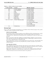
Each byte placed on the data bus represents either a command or a data byte. If the Attention (ATN) interface
management line is TRUE while the data is transferred, then the data bus is carrying a bus command which is
to be received by every GPIB device. If ATN is FALSE, then a data byte is being transferred and only the active
listeners will receive that byte.
Data Byte Transfer Control Bus Description
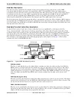
Control of the transfer of each byte of data on the data bus is accomplished by a technique called the
“three-wire handshake”, which involves the three signal lines of the Data Byte Transfer Control Bus. This
technique forces data transfers at the speed of the slowest listener, which ensures data integrity in multiple
listener transfers. One line (DAV) is controlled by the talker, while the other two (NRFD and NDAC) are
wired-OR lines shared by all active listeners. The handshake lines, like the other GPIB lines, are active low.
The technique is described briefly in the following paragraphs and is depicted in
. For further
information, refer to ANSI/IEEE Std 488.1.
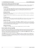
DAV (Data Valid)
This line is controlled by the active talker. Before sending any data, the talker verifies that NDAC is
TRUE (active low) which indicates that all listeners have accepted the previous data byte. The talker
then places a byte on the data lines and waits until NRFD is FALSE (high) which indicates that all
addressed listeners are ready to accept the information. When both NRFD and NDAC are in the proper
state, the talker sets the DAV line TRUE (active low) to indicate that the data on the bus is valid
(stable).
NRFD (Not Ready For Data)
This line is used by the listeners to inform the talker when they are ready to accept new data. The talker
must wait for each listener to set the NRFD line FALSE (high) which they will do at their own rate. This
assures that all devices that are to accept the data are ready to receive it.
NDAC (Not Data Accepted)
This line is also controlled by the listeners and is used to inform the talker that each device addressed to
listen has accepted the data. Each device releases NDAC at its own rate, but NDAC will not go FALSE
(high) until the slowest listener has accepted the data byte.
Figure 1-2.
Typical GPIB Handshake Operation
1st Data Byte
2nd Data Byte
Valid
Not
Valid
Valid
Not
Valid
All
Ready
None
Ready
All
Ready
None
Ready
All
Accept
None
Accept
None
Accept
All
Accept
DIO1-DIO8
(composite)
DAV
NRFD
NDAC
Summary of Contents for MG369 C Series
Page 2: ......
Page 6: ...Contents 4 PN 10370 10374 Rev F MG369xC GPIB PM ...
Page 262: ...A 34 PN 10370 10374 Rev F MG369xC GPIB PM ...
Page 264: ...Index 2 PN 10370 10374 Rev F MG369xC GPIB PM ...
Page 265: ......

