Angelo Po 1G1CP2G Use And Installation  Manual Download Page 15

C1

39

60

330

0_

1.f

m

- 13 - 

IT

AUS

DE

FR

ES

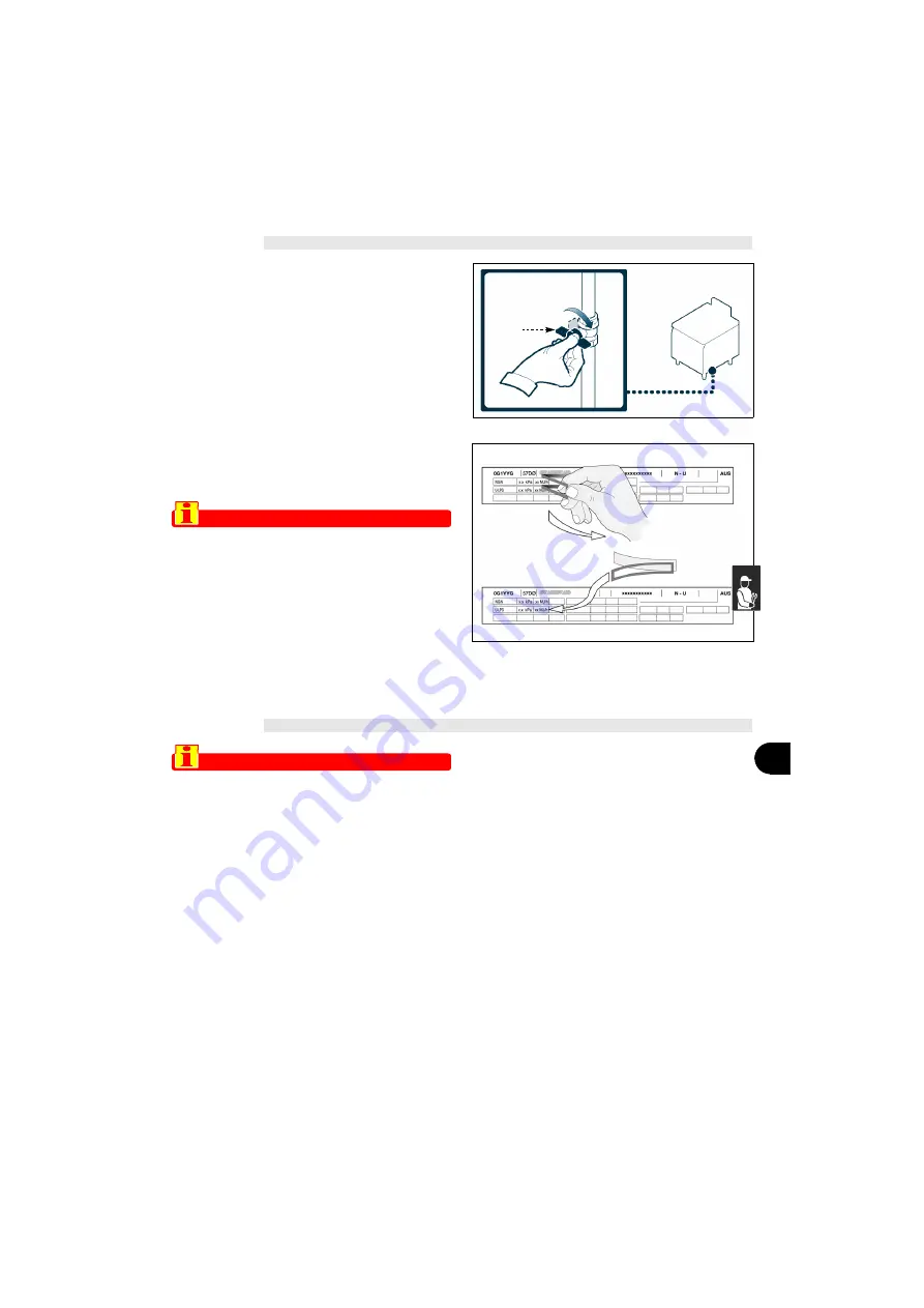
CONVERSION OF THE GAS SUPPLY

The constructor has tested the appliance with its own
mains  gas,  identified  by  the  sticker  applied  to  the
nameplate. 
If the type of gas to be connected is different from that
used for testing, proceed as follows.

1 - Turn off the gas supply tap (

A

).

2 - Change the burner nozzle (see page 16).
3 - Change the pilot light nozzle (see page 16).
4 - Adjust  the  minimum  setting  on  the  gas  control

valve (see page 14).

5 - If  necessary, adjust  the  burner primary  air   (see

page 15).

6 - Remove the sticker from the nameplate and ap-

ply the new one to identify the gas being used. 

Important

On completion of the operation, make sure
that there are no gas leaks or malfunc-
tions.If converting from Natural Gas to Uni-
versal LPG make sure the Natural Gas
Regulator is removed.

TESTING OF THE APPLIANCE

Important

Before it is put into service, the system
must be tested to check the operating con-
ditions of every single component and
identify any malfunctions. In this stage, it is
important to check that all health and safety
requirements have been complied with in
full. 

To test the system, make the following checks:

1 - turn on the gas supply tap and check that the con-

nections are right;

2 - check  that  the  mains  gas  is  the  same  as  that

used  for  commissioning  of  the  appliance,  and
carry  out  the  conversion  procedure  if  neces-
sary (see page 13);

3 - check that the burner is switching on correctly and

its combustion;

4 - check the gas pressure and flow-rate at minimum

and  maximum  settings  and  adjust  if  necessary
(see page 14);

5 - check  that  the  safety  thermocouple  is  working

correctly;

6 - check that there are no gas leaks;
7 - check that the nameplates specify the correct gas

for the country of use.

After  testing,  if  necessary  instruct  the  user  in  all  the

skills necessary for putting the appliance into opera-

tion  in conditions  of  safety,  in  accordance  with  legal

requirements. 

A

IDM-3960200240.tif

A.po_Convers_gas_aus.tif

Summary of Contents for 1G1CP2G

Page 1: ...3005340 C139603300_1 fm AUS PASTA COOKER 1G1CP2G USE AND INSTALLATION MANUAL ...

Page 2: ...Contact for Sales or Service Angelo Po Catering Equipment Unit 4 15 17 Heatherdale Road Ringwood Victoria 3134 Telephone 03 9874 0440 Facsimile 03 9874 0330 ...

Page 3: ...ng 14 Gaspressure checking 8 Gassupply conversion 13 Gastap greasing 15 Gas checkingpressure 8 Gas connection 12 Generaldescriptionofappliance 3 Greasingthegastap 15 H Handlingandinstallation recommen dationsfor 10 Handlingandlifting 10 IIdentificationofconstructorandappli ance 2 Installationandhandling recommenda tionsfor 10 Installationofappliance 11 Installationofdismantledparts 11 LLengthydown...

Page 4: ...in its own language Ital ian but it may be translated into other languages to meet legal and or commercial requirements A littletimetakentoreadthisinformationwillallowthe preventionofriskstohealthandsafety andtherisk ofeconomiclosses Keep this manual in a clearly identified safe place throughouttheworkinglifeoftheappliance sothatitwill alwaysbeavailablewhenrequiredforconsultation The constructor r...

Page 5: ...professional catering sector Main Parts A Cooking well instainlesssteel B Fume exhaust vent Type A for removal of the fumesgeneratedbytheburner C Burner control knob controls thesupply of gas to theburner D Adjustable water spout directstheflowofwater E Piezoelectric ignition lightstheburner F Water tap regulatestheflowofwater G Height adjustable feet to allow perfect levelling of theappliance H G...

Page 6: ...y devices are properly installed and in good working order SAFETY AND INFORMATION SIGNS Theillustrationshowsthepositionofthesignsprovid ed A Burn hazard watchoutforhotsurfaces B General hazard read the manual carefully beforecarryingoutanyprocedure C General hazard describestheprecautions to be adopted during installation and commis sioning D General hazard describestheprecautions tobeadopteddurin...

Page 7: ...cific sector To maintain hygiene and protect the food proc essed from all forms of contamination all elements in direct or indirect contact with foodstuffs and all surrounding zones must be cleaned thoroughly For these operations use only food approved de tergents and never use flammable products or products which contain substances harmful to health Clean only when reasonably necessary and at the...

Page 8: ...OFF The lighting and turning off procedure is as de scribed below for both burners Lighting 1 Turn on the gas supply tap 2 Press the knob and turn it anti clockwise pos a while at the same time pressing the piezoe lectric ignition knob A repeatedly to light the pilot light Keep the knob pressed for about 15 sec to prime the thermocouple 3 Turn the knob anti clockwise pos b to light the burner N B ...

Page 9: ...e SERVICING 5 RECOMMENDATIONS FOR SERVICING Keep the appliance at peak efficiency by carrying out the scheduled servicing procedures recom mended by the constructor Proper servicing will al low the best performance a longer working life and constant maintenance of safety requirements Caution warning Before carrying out any servicing procedure activate all the safety devices provided and decide whe...

Page 10: ...ke special care not to damage stainless steel surfaces In particular avoid the use of corro sive products and do not use abrasive materials or sharp tools 4 Remove food residues immediately before they set 5 Remove the limescale deposits which may form on some of the appliance s surfaces CHECKING GAS PRESSURE To carry out this opera tion proceed as fol lows 1 Turn off the gas supply tap 2 Pull off...

Page 11: ...ne out Turn off the gas supply tap and ventilate the room The pilot light does not ignite The spark ignition devices are not working Check that the ignition devices are in good working order Light by hand with a naked light Contact the after sales service Air in pipelines due to long period out of use Make more attempts to light the flame The pilot light goes out The thermocouple has not warmed up...

Page 12: ...ng carries all information necessary for loading and unloading When unpacking check that all components are present in the correct quan tities and are undamaged The packaging material must be properly dis posed of in accordance with legal requirements TRANSPORT Different means of transport may be used depend ing partly on the destination The chart shows the most commonly used alterna tives During ...

Page 13: ...rom production of the general layout Before starting these stages as well as deciding the place of installation if necessary the person authorised to carry out these operations must organise a safety plan to protect the people directly in volved and he must also ensure strict compliance with all legal requirements especially those relat ing to mobile work sites The place of installation must have ...

Page 14: ...s appliance shall be installed only by authorised personnel and in ac cordance with the manufacturer s instal lation instructions local gas fitting regulations municipal building codes water supply regulations electrical wir ing regulations AS 5601 AG 601 Gas Installa tions and any other statutory regulations A IDM 3960330120 tif A IDM 3960200230 tif Always install a quick closing ON OFF valve A n...

Page 15: ...o service the system must be tested to check the operating con ditions of every single component and identify any malfunctions In this stage it is important to check that all health and safety requirements have been complied with in full Totestthesystem makethefollowingchecks 1 turnonthegassupplytapandcheckthat thecon nectionsareright 2 check that the mains gas is the same as that used for commiss...

Page 16: ...ol panel D 5 Turn the screw to open the pressure connection E 6 Connect the pressure gauge F to the pressure test point E 7 Turn the gas supply tap back on 8 Light the burner and turn the knob to the mini mum flame setting 9 Fit the minimum flow injector G see table pag II Ø 3 1 screwing it fully down 10 Slowly unscrew the injector G until the pres sure reading complies with the values in the ta b...

Page 17: ... thecap F thecontrolpan el D andtheknobs AandB REPLACING PARTS 9 RECOMMENDATIONS FOR REPLACING PARTS Beforecarryingout anyreplacementprocedure acti vate all the safety devices provided and decide whether staff at work and those in the vicinity should be informed In particular turn off the gas supply tap and prevent access to all devices which might cause unexpectedhealthandsafetyhazardsifturnedon ...

Page 18: ... A 3 Unscrewtheunion B 4 Extractthenozzle C andreplaceitwiththe one suitable for the type of gas in use see tableatbackofmanual 5 Screw the union B back in place and close the door A DECOMMISSIONING THE APPLIANCE Important This operation must be carried out by skilled operatives in compliance with the le gal requirements with regard to safety at work Never dump non biodegradable materials lubricat...

Page 19: ...CT39603300_1 fm I ANNEXES Modello Model Modelle ModËle Modelo Burner Total Gas consumption 40 MJ h NGN ULPG 1G1CP2G N 2 80 MJ h 80 MJ h CONNECTION CARD IDM 3960330100_1 tif ...

Page 20: ...ass test point pressure 4 Pilot injector size 5 Iron Ring holes N G C 2 T G C 3 Pilot flame Iron Ring GAS TPP 1 Supply pressure G C Ø 2 1 G C Ø 3 1 p 3 2 Ø 4 Ø 5 NGN 0 8 kPa 1 13 kPa 80 MJ h 3 20 mm 40 MJ h 1 30 mm adj pressure 0 13 kPa 0 40 mm 6 holes x 5 5 mm ULPG 2 75 kPa 2 75 kPa 80 MJ h 1 70 mm 40 MJ h 1 30 mm NO adj All screw 0 25 mm 6 holes x 5 5 mm ...

Reviews: