15
Electronics Assembly Instructions
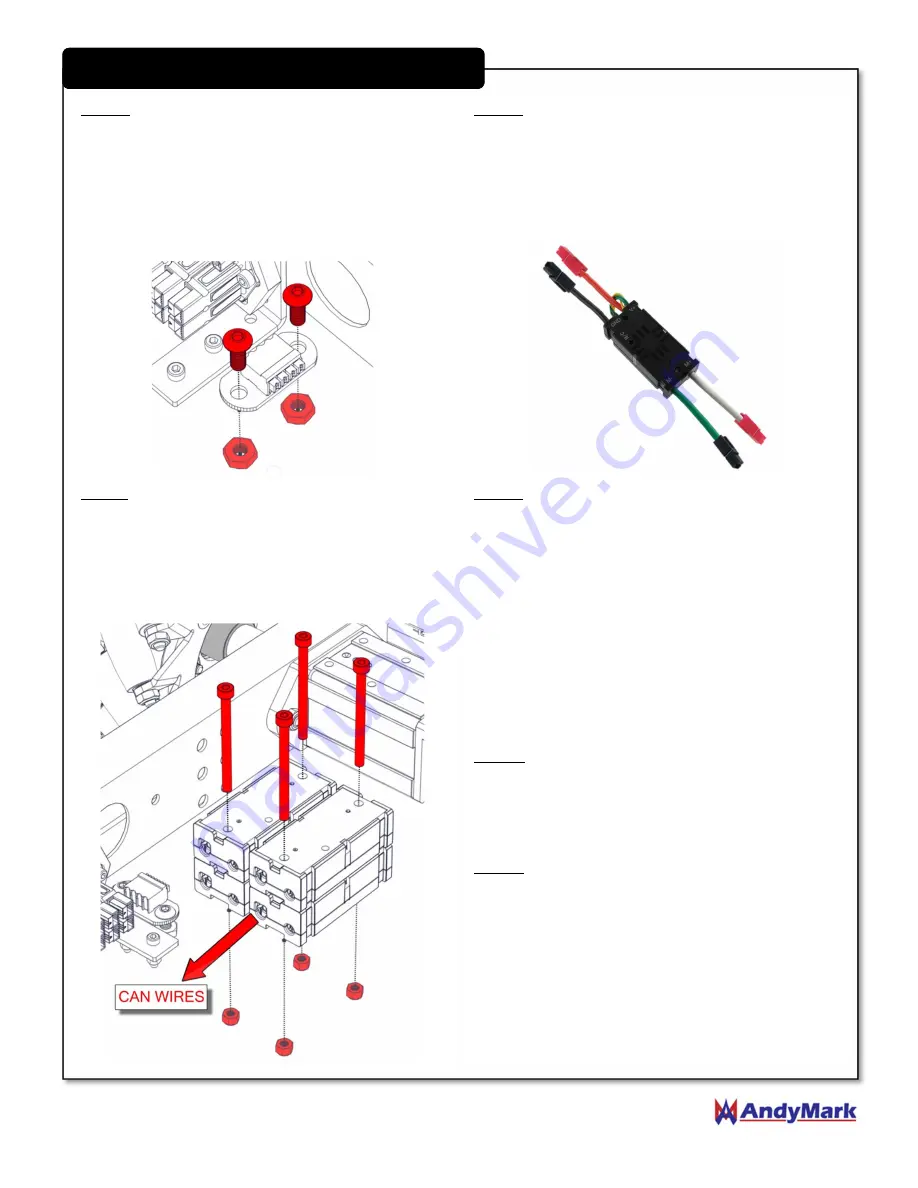
Step 4:
Attach the CAN Connector (am-4130) to the
Bottom Plate using two (2) #10-32 x 0.5 long inch
Button Head Cap Screws (am-1512) and #10-32
Nylock Jam Nuts (am-1063) on the underside of the
Bottom Plate. Be sure to orient the CAN Connector
such that the wire terminals face away from the
PowerPole Distribution Board.
Step 5:
Add PowerPoles (am-2198) to the four power
leads on each Victor SPX. Red PowerPoles should be
added to the Red and White leads and black
PowerPoles should be added to the Black and Green
leads. A PowerPole Crimp Tool (am-2554) (sold
separately) should be used to ensure a proper crimp.
Step 6:
Add four (4) Victor SPX Speed Controllers (am-
3748) in two stacks of two with the CAN wires
oriented facing towards the CAN Connector. Use four
(4) M4x50 Socket Head Cap Screws (am-1401) and M4
Nylock Nuts (am-1435) to secure the controllers to
the top of the Bottom Plate.
Step 7:
Cut one pair of CAN (yellow and green) wires
on one of the bottom Victors to approximately 3
inches long. Save the cut off wire for use in Step 9.
Strip the ends of the remaining wires and crimp 20
AWG White Ferrules (am-3738_20) onto each wire.
Insert the yellow wire into the CAN Connector in one
of the “HI” terminals and the green wire into one of
the “LO” terminals. Insert the legs of the CAN Resistor
(am-4111) into the remaining “HI” and “LO”
terminals.
Step 8:
Connect the remaining CAN wires together
leaving one pair (from any Victor) open. Secure the
connections with the provided retainer clips
Step 9:
Connect the cut off wire from Step 7 to the
remaining open pair of wires from Step 8. Strip the
cut ends of the pair of wires and crimp 20 AWG White
Ferrules (am-3738_20) onto each wire.


