background image

11-APR-06 

Rev E 

OMACS3000 


 20 of 51


System Screens


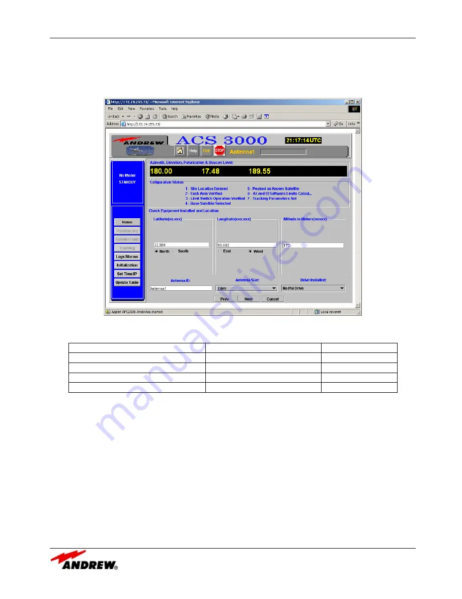
The pol motor type is selected from a pull down menu. The valid pol motor types are: no pol motor installed, 

single speed (1:1 ratio) pol motor, and dual speed (2:1 ratio) pol motor.   Refer to Table 1 to determine the 

appropriate pol motor ratio.  


Figure 11: Initialize Site Location Screen 


Antenna Size 

Polarization Drive P/N 

Ratio 

3.6M, 4.5M 

PK5PF-100 

1:1 

3.7M, 5.6M Ku 

PK5DRA 

1:1 

4.9M, 6.5M 

PK65DR 

2:1 

7.3M, 7.6M, 8.1M, 9.3M, 9.4M 

PK9DRA 

2:1 

Table 1:  Antenna Size to Pol Motor Ratio 


When the location boxes have been filled in and the antenna ID, antenna size, and pol motor type selected, 

entering the NEXT button will save the information and continue initialization. 


Visible Satellites Computed 


Figure 12 is the second screen in the Initialization Wizard process. This screen is displayed when a valid site 

location screen has been entered. This is an information-only screen and lets the operator know how many 

satellites are in the current satellite table and to which hemisphere the site is located. If the hemisphere is 

incorrect, he must repeat the first step and enter the correct site information. Selecting the Prev button will 

allow the operator to re-enter the Site Location. Choosing the Next button will continue the Initialization 

Wizard process by downloading to the PC the satellite table used for initialization.  Figure 13 displays the 

expected popup window that notifies the operator of the action completed.  Selecting the OK button on the 

popup window will continue the process. 


Summary of Contents for ACS3000

Page 1: ...reet FAX U S A 1 800 349 5444 U S A Canada Mexico 1 800 255 1479 Orland Park IL U S A 60462 Internet http www andrew com U K 0800 250055 Other Europe 44 1592 782612 Printed in U S A April 11 2006 Copy...

Page 2: ...CPU IP Setup 11 Regional Options Setup 12 System Screens 13 ACS3000 Screens 13 Home Screen System Not Initialized 13 Home Screen System Initialized 13 Home Screen Hand Held Connected 14 Set Time IP 1...

Page 3: ...ing Summary 35 Satellite Table Screens 36 Satellite Table Screen 37 Working Satellite Table Screen 38 Satellite Entry Edit 39 Logs Alarms 40 Log Screen 41 Alarm Screen 42 Alarm and Events Descriptions...

Page 4: ...dware Limits Screen 25 Figure 18 Select Base Satellite Screen 26 Figure 19 Peak on Base Satellite Screen 28 Figure 20 Automated Set Software Limits Screen 29 Figure 21 Validate Automated Software Limi...

Page 5: ...ws the antenna ramp up in speed as the antenna is commanded to move to a new target satellite yet move at low speed when tracking and peaking up on a satellite NORAD and INTELSAT program track modes a...

Page 6: ...ubset of those satellites that are visible to the particular antenna given the antenna latitude and longitude Using this subset the operator may select a specific satellite to point at and may reposit...

Page 7: ...D DS8 Low Temperature Warning Active RED LED Extinguished DS7 Low EL Status Switch Activated Illuminated steady RED DS6 POL CCW Limit Switch Activated Illuminated steady RED DS5 POL CW Limit Switch Ac...

Page 8: ...ted value of each resolver signal to the MPU 17 The RES 2 provides the following indicators DS 1 EL CEN Illuminates steady YELLOW when the EL resolver is reading center of the R D range 2 degrees A sl...

Page 9: ...ntenna Display Unit Users Guide Power Environmental Description LMKVS CPU Operational Temperature 40 to 50 C If heater is off internal temperature must be 0 C before operation can begin Storage Temper...

Page 10: ...10 of 51 System Description Dimensions 19 W x 1 75 H x 4 D Weight 3 lbs Approvals EN 60950 CE EN 61326 Class A UL 60950 FCC Part 15 Class A Power 85 250 VAC 0 35 Amps 1 Phase 50 440 Hz Neutral Requir...

Page 11: ...up the Internet connection options on his browser The operator should contact his IT manager in order to verify that the LAN to be used is compatible with the IP address assigned to the ACS300 system...

Page 12: ...ecuted in that case After the telnet session is dropped verify the change in the antenna controller box IP address by pinging the new address from the MS DOS window Regional Options Setup In order for...

Page 13: ...at describe system information and buttons that can be selected to bring up the other screens Figure 3 shows the Home Screen when the antenna controller system first comes up before it has been initia...

Page 14: ...M C port If line four is displayed it will report in yellow the status message Hand Held or Monitor Only See Figure 5 Figure 4 Home Screen System Is Initialized Home Screen Hand Held Connected Figure...

Page 15: ...hould be the first screen requested in order to synchronize the antenna controller box to UTC time The Beacon Interface Box default address is 192 168 1 77 Note It must match the IP address of the Bea...

Page 16: ...the Initialization Wizard entry screen The operator may select Test Only Start Initialization or Review Parameters The Test Only button will bring up a password protected screen that is used for syste...

Page 17: ...ization Entry Screen Test Only Password Protection Screen The Test Only button brings up Figure 8 the Test Only Password protection screen The operator must enter the correct password in order to brin...

Page 18: ...OMATICALLY change limits and motor commands to accommodate for the antenna being located in the Southern Hemisphere Note The ACS3000 will assume a Northern Hemisphere location until the site location...

Page 19: ...capability so it is important to get a valid GPS type of accuracy of the antenna location latitude and longitude The antenna ID will identify the antenna under control by displaying the antenna ID at...

Page 20: ...nformation and continue initialization Visible Satellites Computed Figure 12 is the second screen in the Initialization Wizard process This screen is displayed when a valid site location screen has be...

Page 21: ...or MUST place an observer near the antenna who can be in constant communication with the antenna controller operator The observer should be able to see in which direction the antenna moves and whether...

Page 22: ...next step Figure 14 Verify Jog Direction Screen Verify Az and El Hardware Limits This step in the Initialization Wizard also requires an antenna observer who is in contact with the antenna controller...

Page 23: ...ed Pol Drive Hardware Limits If a single speed 1 1 ratio pol drive is installed the operator moves to the counter clockwise limit as directed by the screen See Figure 16 The operator will jog until th...

Page 24: ...est for the operator to manually rotate the pol resolver to read 1 0 degree The operator or observer must manually rotate the pol resolver on the antenna during initialization setup in order to guaran...

Page 25: ...e satellites in black font while satellites in red font are not visible from the current site location However during the first time an antenna is initialized all satellites may be displayed as red si...

Page 26: ...ate antenna look angles for the antenna when it is peaked he may modify the look angles in the Satellite Info Box and use the more accurate angles to set the az and el offsets The satellite may be acq...

Page 27: ...over the range of 2 6 While moving the antenna monitor the Spectrum Analyzer for signals 7 If a signal is detected maximize the received signal level by tweaking the antenna azimuth and elevation angl...

Page 28: ...f 51 System Screens Figure 19 Peak on Base Satellite Screen First Scan Third Scan Antenna Scans for Satellite Acquisition Start Location Point First Scan Second Third Scan Start Point 2 in Azimuth Ele...

Page 29: ...ware limits check boxes to appear The process slews the antenna to the hardware limits and then sets the software limits 1 degree in from the hardware limit Since the antenna must be physically slewed...

Page 30: ...tracking parameters setup see Figure 22 The beacon slope is the multiplier used to convert the beacon receiver voltage into dBs The beacon offset is the value that will be added to the beacon data in...

Page 31: ...FG button saves the configuration data to a file on the PC and overwrites any configuration file already saved on the PC The saved configuration file will be written to the C drive onto a directory na...

Page 32: ...e been completed and the review parameters screen has been canceled Note that each of the configuration status segments is checked and that the position jog and tracking buttons are no longer grayed o...

Page 33: ...en the operator wishes to jog the antenna at a faster rate in order to cover more distance quickly The Stop command is used to terminate a move in progress The Stop command is not necessary when the a...

Page 34: ...tor to copy the position log from the ACS3000 server down to a local drive on the PC The file will be saved as C ACS3000 antennaID position log The Jog with Arrow Keys panel allows the operator to ena...

Page 35: ...f no NORAD data has been entered into the satellite table for the selected satellite or if the data in the satellite table is invalid the system will revert to Standby mode INTELSAT Track needs curren...

Page 36: ...also be accurate Significant errors may result if time and location are not correct INTELSAT is intended to help find a target For antennas with beamwidths less than 0 25 degrees some signal loss may...

Page 37: ...is save will overwrite the currently loaded local satellite table that was uploaded when the browser was first initiated This allows the operator to save updates and modifications to a local file Figu...

Page 38: ...satellite from the working satellite table select the satellite as the base satellite and move to that satellite or add a new satellite to the satellite table and tag it as a working satellite entry...

Page 39: ...an then modify any or all parameters in the satellite table entry as listed These parameters may be typed in or copied and pasted from another screen The cut and paste capabilities are dependent on us...

Page 40: ...al not the logging of the alarms See Figure 31 The Enable Java Console Output to File option will write all Java console output to a local file The Disable Java Console Output to File option will disc...

Page 41: ...n the operator first selects the Logs Alarms button the system reads the complete event log and orders the events from the most current to the oldest Once the full event log is read any new events tha...

Page 42: ...ogs screen The Logs screen will record all events and the Alarm screen will record only critical events System not initialized System not initialized operator must run the startup wizard Java Sockets...

Page 43: ...tware Limits Az West Software Limits reached MCU error ON or OFF El Up Software Limits El Up Software Limits reached MCU error ON or OFF El Down Software Limits El Down Software Limits reached MCU err...

Page 44: ...been selected Motor movement stopped MCU detected motor movement stopped Invalid Intelsat Track mode parameters Invalid Intelsat Track mode parameters tracking turned off Invalid NORAD Track mode para...

Page 45: ...A track move did not complete in time allotted so the move is repeated Track move timeout Track move timeout Did not reach commanded position after three move repeats Scan cycle time nnn scan cycle l...

Page 46: ...The Update Table button on the control panel allows the operator to update the satellite table by merging new NORAD data with the currently loaded satellite table All working entries will be preserve...

Page 47: ...11 APR 06 Rev E OMACS3000 47 of 51 System Screens Figure 34 Celestrack Web Site...

Page 48: ...ontinued at any time The government sponsored site for the two line element is http www space track org perl login pl and must be accessed through a valid registration and login procedure Go to that s...

Page 49: ...tellite table Figure 37 Alternate Update Satellite Table Popup Window INTELSAT data in the satellite table must be updated on a satellite by satellite basis and entered using the edit satellite data o...

Page 50: ...11 APR 06 Rev E OMACS3000 50 of 51 System Screens Figure 38 Update Software Button Figure 39 Update Software Confirmation Figure 40 Update Software Request Denied...

Page 51: ...update has been completed and that the browser must be closed as the ACU system will have to reboot for the update to complete After the operator allows enough time for the system to reboot he may br...

Reviews: