


Andrew Corporation
10500 West 153rd Street
Orland Park, IL U.S.A. 60462
Telephone: 708-349-3300
FAX (U.S.A.): 1-800-349-5444
Internet: http://www.andrew.com
Customer Service, 24 hours: U.S.A. • Canada • Mexico: 1-800-255-1479
U.K.: 0800 250055 • Republic of Ireland: 1 800 535358
Other Europe: +44 1592 782612
Printed in U.S.A. 01/05
Copyright © 2005 by Andrew Corporation
Installation, Operation and Maintenance
Bulletin OM93
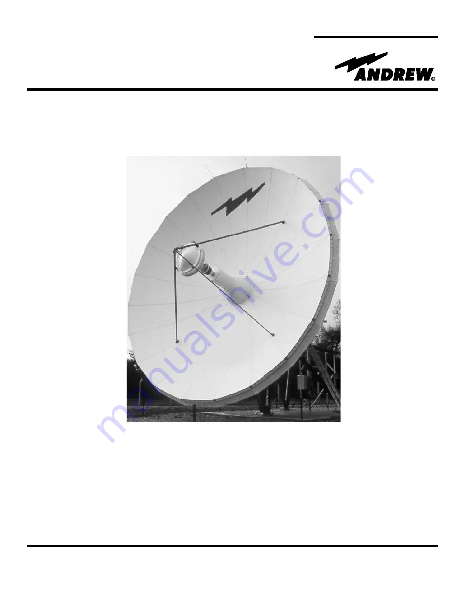
Type ES93( )
9.3-Meter ESA
9.3-Meter Earth Station Antenna
Revision D


