background image

CO Clear 
User Manual 

Int. Approved 


Document ref: ACO-810-28 

October 2018 

Page 20 of 24


Copyright © 2006 Analox Ltd. All Rights Reserved. 


Commercial in Confidence 

10.6


Adjusting alarm set points 


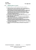
The following procedure is very similar for setting either Alarm 1 or Alarm 2: 


Whilst the 

Analox

 CO 

Clear

 is switched on, enter Technician Mode by 

pressing the mode switch 3 times. If entered successfully the green LED 
will flash off for 1.5 seconds and on for 0.5 of a second. 


From Technician Mode, press the Mode switch 2 times to set Alarm 1 or 3 
times to set Alarm 2. The buzzer will bleep on each press.  If this is done 
successfully, the instrument will show the Fault indicator and the 
appropriate Alarm indicator. If this is done inadvertently, or if another 
mode is selected, press the Mode switch once to return to Technician 
Mode and then repeat this selection. 


The display will indicate the present value of the alarm. 


Press the Mode switch twice to proceed to define a new setting, or once to 
abort and return to Technician Mode. 


When setting Alarm 1 or Alarm 2, the display will show the maximum 
display value (full scale).  


Press and hold the Mode switch. The displayed value will count down at 
approximately one count per second.  Release the switch when the 
displayed value is equal to the desired alarm value. 


Upon release of the Mode switch, the display will continue to show the 
new value.  Accept the new setting by pressing the Mode switch twice, or 
alternatively ignore the new setting by pressing the switch once.  This will 
return to the Technician Mode. 


To exit from Technician Mode, press the Mode switch once.  The 

Analox

 CO 

Clear

 then restarts by performing the normal power on sequence (4 

flashes). 

Summary of Contents for CO Clear

Page 1: ...Analox Ltd 15 Ellerbeck Court Stokesley Business Park North Yorkshire TS9 5PT UK T 44 0 1642 711400 F 44 0 1642 713900 W www analox net E info analox net CO Clear User Manual Commercial in Confidence...

Page 2: ......

Page 3: ...ble 10 6 1 AC supply models 10 6 2 DC supply models 10 6 3 Alarm repeaters 10 6 4 Alarm relay output models 10 6 5 Relay wiring 11 6 6 4 to 20mA output models 12 7 Operation 13 7 1 Normal operation 13...

Page 4: ...re re use Obtain medical advice if continued irritation Ingestion Corrosive May cause sore throat abdominal pain nausea and severe burns of the mouth throat and stomach and may be fatal If swallowed D...

Page 5: ...V AC and 230V AC Versions Less than 5W 24V DC Version Mains frequency 50 60Hz The Remote Alarm Repeater has ingress protection to IP43 direct sprays of water up to 60 from the vertical in accordance w...

Page 6: ...r please check you have the following 1 Analox CO Clear main unit and Alarm Repeater 2 User Manual 3 Test Certificate 4 Rawl Plugs and Screws for Wall Mounting 5 Drilling Template 6 Analox CO Clear Wi...

Page 7: ...10 250V AC supply 2 110 120V AC supply 3 9 24V DC supply The Analox CO Clear is intended to be used as a permanent installation It provides a digital readout of Carbon Monoxide and 2 audio and visual...

Page 8: ...e CO cell increases by what we call the compensation factor see Table 1 For example if a CO Clear He measured 3ppm CO in a tank containing 99 He the actual CO content would be 2 1ppm 3 x 0 7 2 1ppm Th...

Page 9: ...wall and use the Rawl plugs and screws provided to mount the unit It is not necessary to dismantle the Analox CO Clear main unit in any way prior to installation You need to ensure the mains plug fus...

Page 10: ...ear enclosure An 8 metre 8 core cable is pre wired to the Analox CO Clear on units to be fitted with an alarm repeater This ensures that for a basic installation there is no need to dismantle the Anal...

Page 11: ...ened Test that the cable is adequately gripped by the cable gland Ensure that the cable is suitable for purpose the load is within the limits of the relay 240VAC 28VDC 2Amps and the insulation of the...

Page 12: ...20mA output models You may have ordered your Analox CO Clear with a 4 to 20mA output A 2m cable is factory fitted to the instrument The 4 to 20mA output current is generated by the instrument The cus...

Page 13: ...n the first alarm level then the Alarm 1 indicator will begin to flash and the buzzer will sound at its slow speed If the measured concentration of CO continues to rise above the second alarm level th...

Page 14: ...ollowing specifications Maximum inlet pressure 200Bar Outlet pressure 0 3 BarG For systems where 1 4 pipe work is used the push fitting in the sensor housing must be swapped out Remove the sensor hous...

Page 15: ...e This housing allows the Carbon Monoxide sensor to be easily replaced when necessary To ensure continuous operation it is recommended to replace the sensor at 18 month intervals The procedure for rep...

Page 16: ...l only connect in one orientation NOTE THE NEW CARBON MONOXIDE SENSOR IS SUPPLIED IN A HOUSING READY TO BE FITTED Carefully feed the sensor wire and sensor housing through into the bulkhead and then f...

Page 17: ...to perform a calibration check you will need the following equipment 10 1 0 to 10ppm in nitrogen range calibration gases Air and Nitrox Kit for use with Analox CO Clear 1 Zero Gas 20 9 O2 in N2 balan...

Page 18: ...the Zero Calibration the Red Alarm 1 LED will turn off and the Green LED will continue to flash Wait one minute for the instrument to adjust When the instrument has a new calibration value the buzzer...

Page 19: ...t has accepted the new Carbon Monoxide value To return to normal operation press the mode switch once The LED s and buzzer will illuminate sound 4 times before returning to normal operation Fully clos...

Page 20: ...ther mode is selected press the Mode switch once to return to Technician Mode and then repeat this selection The display will indicate the present value of the alarm Press the Mode switch twice to pro...

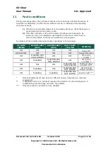
Page 21: ...t the problem contact your qualified service engineer A summary of the indicator lamps and buzzer operations is shown below OK LAMP GREEN ALARM1 LAMP RED ALARM2 LAMP RED FAULT LAMP YELLOW MEANING OFF...

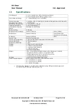
Page 22: ...0x70 mm 6 8x5 11x2 75inches IP Rating Analox CO Clear IP65 Sensor Type Electro Chemical Cell Sensor Life Expected 2 years at Standard Temperature and Pressure Sensor Warranty 9 months graded Electroni...

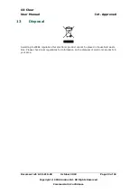
Page 23: ...f 24 Copyright 2006 Analox Ltd All Rights Reserved Commercial in Confidence 13 Disposal According to WEEE regulation this electronic product cannot be placed in household waste bins Please check local...

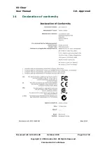
Page 24: ...CO Clear User Manual Int Approved Document ref ACO 810 28 October 2018 Page 24 of 24 Copyright 2006 Analox Ltd All Rights Reserved Commercial in Confidence 14 Declaration of conformity...

Reviews: