UG-1926
Rev. 0 | Page 7 of 20
GETTING STARTED
SOFTWARE INSTALLATION PROCEDURES
Perform the following steps before plugging any of the USB
devices into the PC:
1.
Close all open applications on the PC.
2.
After downloading the
installer from
ftp://ftp.analog.com/pub/microconverter/ADuCM420
, double
click
ADuCM420Installer-V0.1.0.0.exe
and follow the
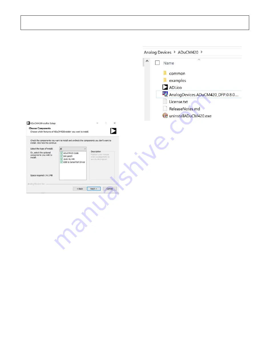
instructions shown in Figure 4. The
ADuCM420Installer
Setup
window displays the installation method and
component selection, as shown in Figure 4. The end user
license agreement (EULA) is displayed after proceeding
through the
ADuCM420Installer Setup
window. Accepting
the EULA extracts the installer, and rejecting the EULA
cancels the installer.
2584
4-
00
2
Figure 4. Installation Options
3.
After installation, the
\AnalogDevices\ADuCM420
folder
opens. This location contains the
examples
folder that stores
the example codes for the ADuCM420 (see Figure 5).
25844-
0
03
Figure 5. ADuCM420
examples
Folder with Projects
KEIL μVISION5
The Keil μVision5 integrated development environment (IDE)
integrates all the tools necessary to edit, assemble, and debug
code. The fastest way to begin running the Keil IDE is to open
an existing project by using the following steps:
1.
In Keil, click
Project
>
Open Project
.
2.
Browse to the folder where the ADuCM420 software is
installed (
C:\AnalogDevices\ADuCM420...
).
3.
Open the
M420_GPIO.uvprojx
file, located in the
ADuCM420\examples\M420_GPIO\ARM
folder.
Opening the file launches an example project.
4.
Set up the Cortex microcontroller software interface
standard (CMSIS) pack before proceeding through the
source. See the CMSIS Pack in Keil μVision5 section for
details on how to import the CMSIS pack.
5.
Compile and download the source code to the EVAL-
ADUCM420QSP1Z board through the menu bar on the
IDE.
6.
To run the source code, press
RESET
on the EVAL-
ADUCM420QSP1Z board, and then press
RUN
.
7.
When running the code, the green LED on the board
marked
DISPLAY
flashes.


