


User Guide
VSM CLIENT
Rev. 0 | 8 of 20
FIND THE DEVICE ON VSM CLIENT
Take the following steps to find the device on the VSM Client
software:
1.
After installing VSM Client, power on the EVAL-ADPD6000Z
and launch VSM Client.
2.
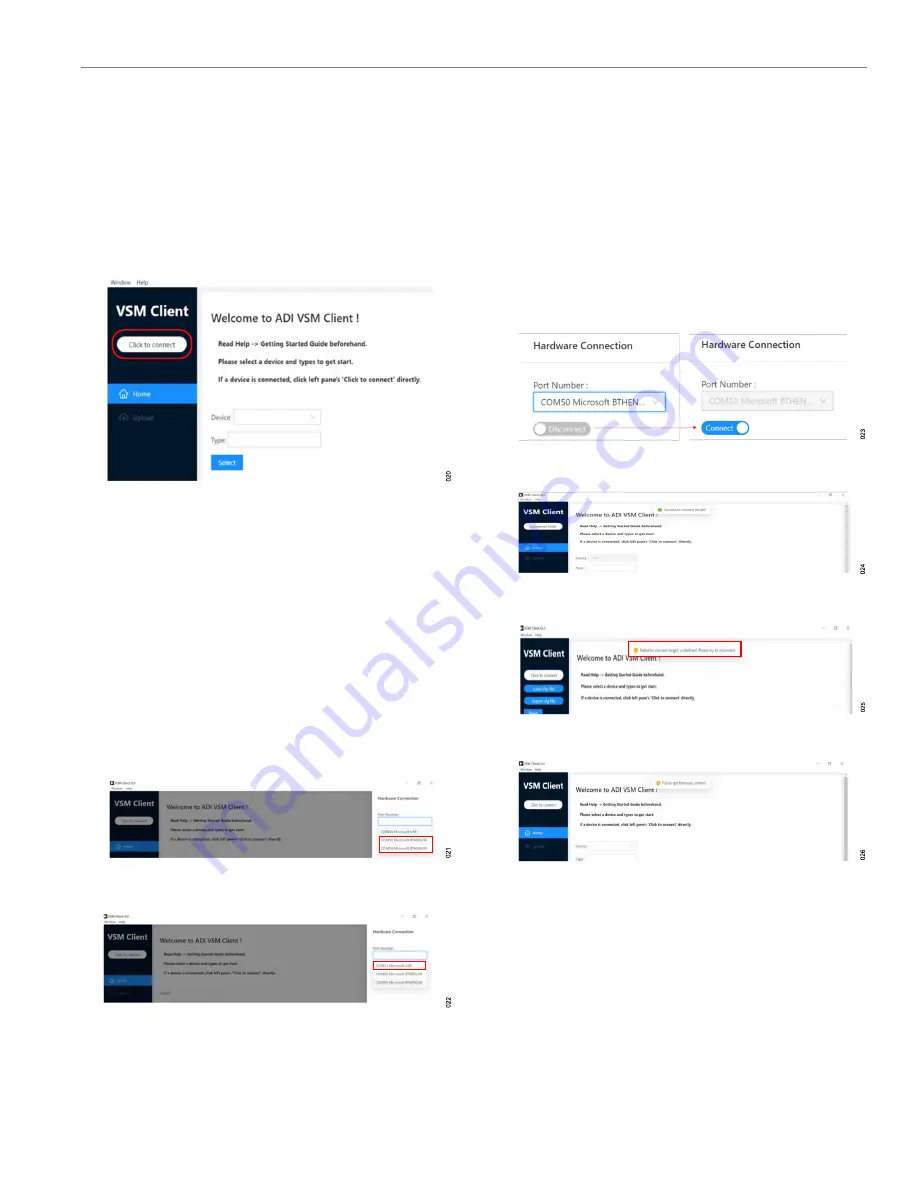
Click
Click to connect
in the start interface of VSM Client (see
).
Figure 20. Start Interface of VSM Client
3.
In the
Hardware Connection
pane, select the communication
(COM) port according to the connection method, as follows:
►
If using a Bluetooth connection, two ports are available. In
, these ports are
COM50
Microsoft BTHENUM
and
COM58 Microsoft BTHENUM
.
Select one of the two ports. If the following steps cannot
be completed successfully with the selected port, select a
different port.
►
If using a cable connection, only one port is available (see
, the port is
COM11 Microsoft USB
.
The COM serial port numbers shown are examples only. Refer
to the
Device Manager
for the COM serial port numbers.
Figure 21. Bluetooth Connection COM Ports
Figure 22. Cable Connection COM Port
4.
Toggle the connection switch to
Connect
(see
).
When connected, a
Success to connect target!
pop-up ap-
pears at the top of the VSM Client window (see
the
Click to connect
button changes to display
Connected
6000
. To disconnect the device, toggle the connection switch to
Disconnect
. The following pop-up messages can appear if the
connection is unsuccessful:
►
Failed to connect target: undefined. Please try to recon-
nect
COM port and reconnect.
►
Fail to get firmware version!
. If this pop-up appears (see
), the firmware version may not match the software
version. Update the firmware in the kit. For details on updat-
ing the firmware, see the EVAL-ADPD6000Z product page.
Figure 23. Toggle Connection Switch
Figure 24. Connection Successful
Figure 25. Failed to Connect Target Error
Figure 26. Failed to Get Firmware Version Error
5.
From the
Type
dropdown menu, select one of three functions:
ECG
,
PPG
, or
BIOZ
). Click
Select
to enter the
configuration interface.


