background image

UG-1274 

EVAL-ADPD188BIZ-SK

 User Guide


Rev. 0 | Page 4 of 10 

If the firmware must be updated, take the following steps: 

1.


Download and install the latest DfuSe USB device 
firmware upgrade software. 

2.


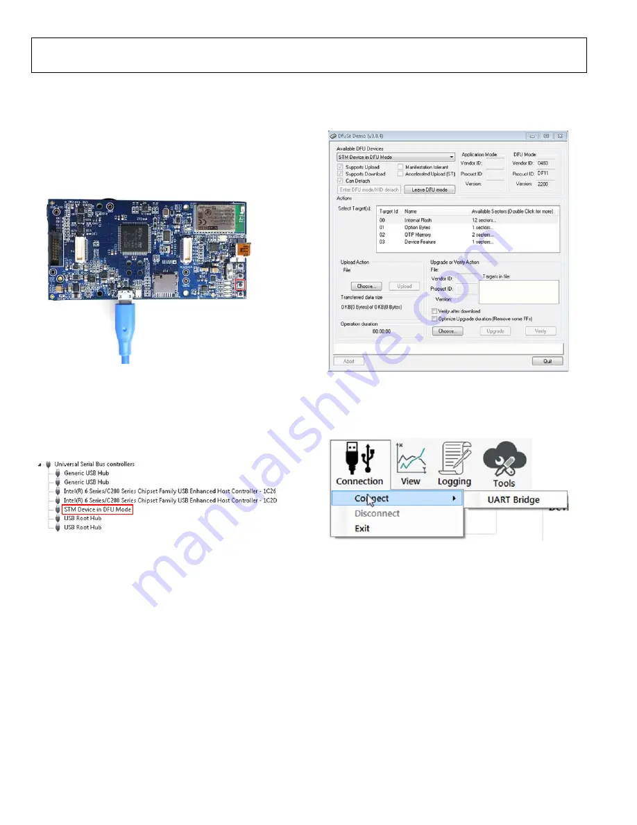
Plug in a micro USB cable between th

EVAL-ADPDUCZ


and the PC with the power to th

EVAL-ADPDUCZ

 turned 

off (see Figure 6)

3.


Press and hold the 

BOOT0

 button, and switch the power 

switch to the 

ON

 position 

BOOT0
BUTTON

16

75

6-

00

6


Figure 6. Micro USB Connection and 

BOOT0

 Button Used when Upgrading 

Firmware 

4.


Go to 

Device Manager

 > 

Universal Serial Bus controllers


and wait until the PC detects 

STM Device in DFU Mode 

(see Figure 7). If the PC does not detect the STM device in 
DFU mode, then the STM drivers must be manually 
installed to continue updating the firmware. 

1675

6-

0

07


Figure 7. 

STM Device in DFU Mode

 Displayed 

5.


Release the 

BOOT0 

button. 

6.


Open the 

DfuSe Demo

 by going to 

Start

 > 

All Programs 

STMicroelectronics 

DfuSe

 > 

DfuSe Demo

. Figure 8 

shows the 

DfuSe 

demo settings at startup. 

7.


Click the 

Choose

 button from the 

Upgrade or Verify 

Action

 window and select 

Adpd_M4_uC.dfu 

from the 

Firmware

 folder of the downloaded software package. 

8.


Click the 

Upgrade

 button and follow the prompts to upgrade 

the firmware of th

EVAL-ADPDUCZ

 microcontroller board. 

After the firmware updates, connection to the WaveTool completes. 

16756-

008


Figure 8. 

DfuSe 

Demo Settings 

USB UART CONNECTION 

To establish the USB UART connection, use the following menu 
path

: Connection 

Connect

 > 

UART Bridge

16756-

009


Figure 9. UART Connection 

Select the proper COM port to connect the WaveTool to the 
device. If connection via Bluetooth is required, or if there are 
any other connection issues, refer to the 

Applications WaveTool


user guide that is provided in the software package download. 


Summary of Contents for EVAL-ADPD188BIZ-SK

Page 1: ... RESOURCES ADPD188BI data sheet Applications WaveTool software package GENERAL DESCRIPTION The EVAL ADPD188BIZ SK evaluation board provides users with a simple means of evaluating the ADPD188BI optical module for smoke and aerosol detection applications The evaluation system includes the Applications WaveTool graphical user interface GUI providing users with low level and high level configurabilit...

Page 2: ...the Applications WaveTool 3 Connecting the EVAL ADPDUCZ Microcontroller Board and the EVAL ADPD188BIZ SK Evaluation Board 3 Checking the USB Serial Connection in Windows 3 Running the Applications WaveTool 3 Instructions to Load the Firmware 3 USB UART Connection 4 Acquiring Data 5 Selecting the Proper View 5 Load Configuration 5 Optimizing and Running the ADPD188BI 5 Evaluation Board Schematics a...

Page 3: ...PD188BIZ SK CHECKING THE USB SERIAL CONNECTION IN WINDOWS Ensure that the COM port driver is installed correctly To verify proper installation of the COM port driver go to Control Panel All Control Panel Items System Device Manager as shown in Figure 4 In this case the proper COM port selection is USB Serial Port COM16 The EVAL ADPDUCZ microcontroller board uses an FT232 USB universal asynchronous...

Page 4: ... 7 STM Device in DFU Mode Displayed 5 Release the BOOT0 button 6 Open the DfuSe Demo by going to Start All Programs STMicroelectronics DfuSe DfuSe Demo Figure 8 shows the DfuSe demo settings at startup 7 Click the Choose button from the Upgrade or Verify Action window and select Adpd_M4_uC dfu from the Firmware folder of the downloaded software package 8 Click the Upgrade button and follow the pro...

Page 5: ...figuration file from the file dialog box 16756 012 Figure 12 Selecting Load DCFG to Select the Configuration File OPTIMIZING AND RUNNING THE ADPD188BI Using the ADPD188BI_SK dcfg configuration file the ADPD188BI is set up with an infrared IR LED firing in Time Slot A and the blue LED firing in Time Slot B The initial configuration is as shown in Figure 18 Before running the Applications WaveTool a...

Page 6: ...button to set the Time Slot A and Time Slot B raw data values to approximately zero plus or minus the noise that may be present see Figure 17 16756 017 Figure 17 Data View Following Null Offset After these steps are complete the user can begin testing with different aerosols Figure 19 shows the raw output data as well as the blue IR ratio of the response to a jet of smoke spray The EN_MW button ca...

Page 7: ...VAL ADPD188BIZ SK User Guide UG 1274 Rev 0 Page 7 of 10 16756 018 Figure 18 Smoke Device Configuration Smoke Config View 16756 019 Figure 19 Raw Data Response and Blue IR Ratio Measurement of Smoke Spray ...

Page 8: ... 0Ω 10µF VDD_3V 0Ω 0Ω VDD_3V 3PIN_JUMPER_SM LEDX1 CONN1_SPI1_MOSI P1_7 VBOOST VDD_3V 0Ω 0Ω 0 1µF LEDX3 FTSH 108 01 L D K CONN1_TMR0_OUT P0_14 PD_COMM VDD_1 8V VBOOST EXT_SENSOR1 ECG_SP_OUT CONN1_WAKE1 P1_0 CONN1_TMR0_OUT P0_14 LEDX1 LEDX2 CONN1_WAKE1 P1_0 VDD_1 8V VBOOST CONN1_SPI1_MOSI P1_7 CONN1_SPI1_MISO P1_8 CONN1_WAKE0 P0_15 CONN1_SPI1_CS0 P1_9 CONN1_SPI1_CS1 P2_11 SPI1_CS1 VDD_1 8V SDA VDD_1...

Page 9: ...MPER DF40HC 2 5 20DS 0 4V 51 0Ω DF40HC 2 5 20DS 0 4V 51 CONN1_I2C_SCL P0_4 CONN1_I2C_SDA P0_5 CONN1_I2C_SDA P0_5 CONN1_SPI1_MISO P1_8 CONN1_TMR0_OUT P0_14 CONN1_WAKE0 P0_15 VDD_1 8V VDD_1 8V CONN1_I2C_SCL P0_4 CONN1_I2C_SDA P0_5 CONN1_I2C_SCL P0_4 VDD_1 8V CONN1_SPI1_CLK P1_6 CONN1_SPI1_MOSI P1_7 CONN1_SPI1_CS0 P1_9 VDD_3V VLDO3 VLDO1 IOVDD DN CONN2_IOVDD CONN2_ADC0_VIN2 P2_5 VLDO3 SYS_HWRST CONN2...

Page 10: ...her party for any reason Upon discontinuation of use of the Evaluation Board or termination of this Agreement Customer agrees to promptly return the Evaluation Board to ADI ADDITIONAL RESTRICTIONS Customer may not disassemble decompile or reverse engineer chips on the Evaluation Board Customer shall inform ADI of any occurred damages or any modifications or alterations it makes to the Evaluation B...

Reviews: