EVAL-ADIN1110EBZ User Guide
Preliminary UG-XXXX
Rev. PrA | Page 5 of 23
Table 2 shows an overview of the EVAL-ADIN1110EBZ supply
rail current for various operating modes.
Table 2. EVAL-ADIN1110EBZ Quiescent Current
(External Supply Rail = 24V)
Board Status
Typical
Quiescent
Current
ADIN1110 & ADuCM4050 held in hardware reset.
(RESET_N held low via S5)
1 mA
On power-up
(ADIN1110 & ADuCM4050 not held in reset)
8 mA
HARDWARE CONFIGURATION PINS SETUP
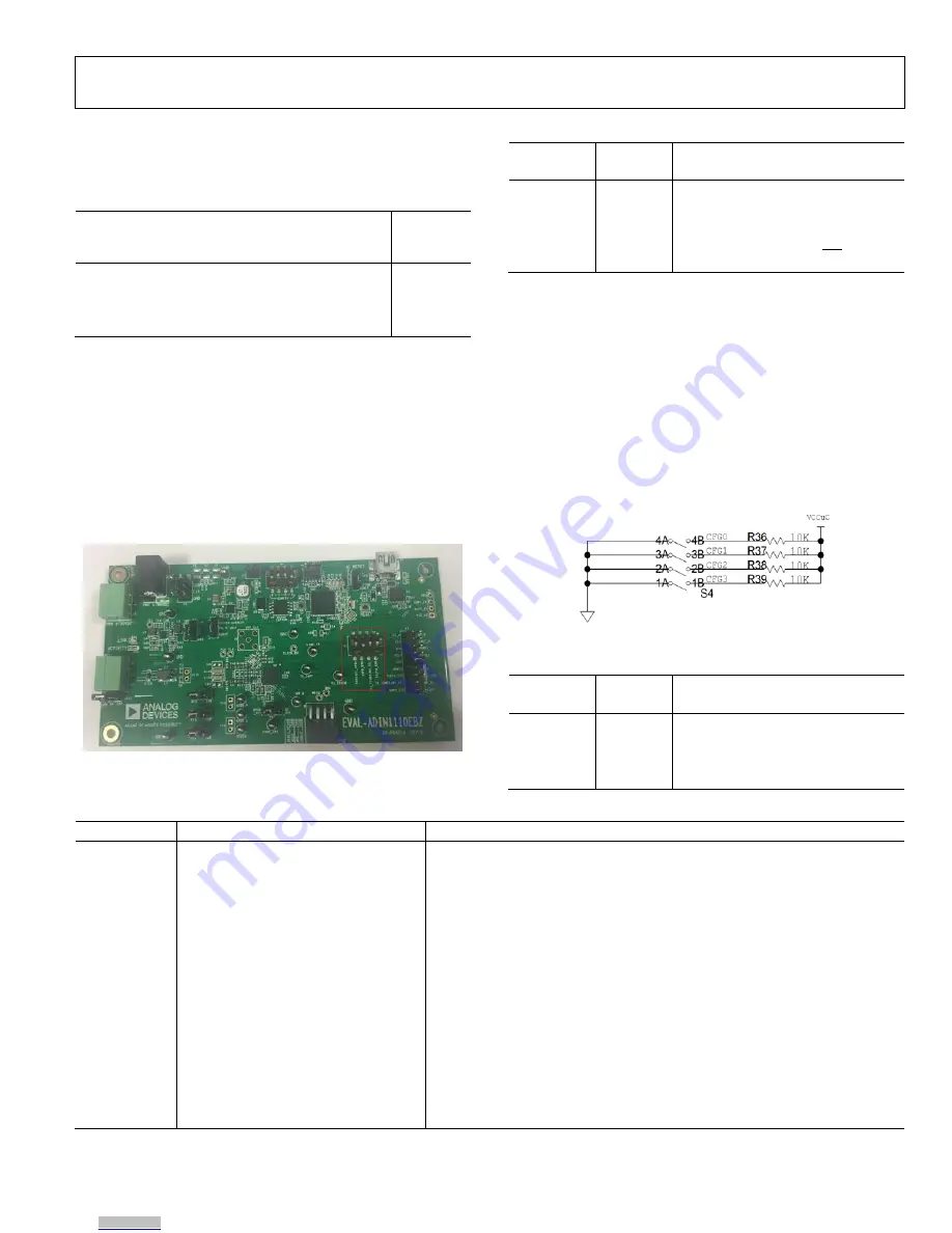
The ADIN1110 hardware configuration pin settings can be
changed by manipulating S1 switch settings found on the right-
hand-side of the EVAL-ADIN1110EBZ board (highlighted in
Figure 6). Table 3 lists the default switch configuration settings
on the board (see ADIN1110 datasheet for full details on
hardware configuration pin functionality). When the switch is
OFF, the hardware configuration pin is pulled low via an
internal pulldown resistor and when the switch in ON, the pin
is pulled high via an external 4.7 kΩ pull-up resistor.
Figure 6. Hardware Configuration Pins Switches Location.
Table 3. Default ADIN1110 H/W Config Switch Position
Switch/
Pin no.
Default
Position
Default Switch Position Function
S1/Pin1
OFF
TX2P4_ENB – 1.0 Vpk-pk/2.4 Vpk-pk
transmit amplitude mode
S1/Pin2
OFF
MS_SEL – Prefer slave selection
S1/Pin3
ON
SWPD_ENB – ADIN1110 not in SWPD
S1/Pin4
OFF
SPI_CFG0 - Use 8-bit CRC on host SPI
ON-BOARD ADUCM4050 MICROCONTROLLER
The EVAL-ADIN1110EBZ has an on-board ADuCM4050
which can be used to read/write to the ADIN1110 MAC-PHY
over the SPI interface using the USB connection. This allows
interaction with the ADIN1110 device via a UART terminal
window.
ADuCM4050 Configuration Switches
The ADuCM4050 has 4 associated configuration switches
which are pulled low when the switch is in the ON position and
pulled high when in the OFF position (Figure 7). By default, all
four configuration switches are ON.
Figure 7. ADuCM4050 Config Switches
Table 4. Default ADuCM4050 Config Switch Position
Switch/
Pin no.
Default
Position
Default Switch Position Function
S4/Pin1
ON (1)
CFG3 – ADuCM4050 Config pin 3
S4/Pin2
ON (1)
CFG2 – ADuCM4050 Config pin 2
S4/Pin3
ON (1)
CFG1 – ADuCM4050 Config pin 1
S4/Pin4
ON (1)
CFG0 – ADuCM4050 Config pin 0
Table 5. ADuCM4050 Config Switch Modes
CFG[3:0]
1
Operating Mode
2
Description
0000
TCP/IP Stack & Web Server, DHCP client,
MAC Addr1
The use of this mode is depicted in Figure 11. In this mode, the TCP/IP stack can
be managed via UART using dynamic IP address allocation. The media
converter board is then used to convert 10BASE-T1L to 10BASE-T ethernet, for
which common web browsers can be used to access the associated
information. MAC address 1 is used.
0001
TCP/IP Stack & Web Server, Fixed IP,
MAC Addr1
This is a similar mode to the previous one except fixed IP address allocation is
used. MAC address 1 is used.
0010
Not defined
The ADuCM4050 makes no autonomous attempt to interact with the
ADIN1110 MAC-PHY.
0011
Not defined
The ADuCM4050 makes no autonomous attempt to interact with the
ADIN1110 MAC-PHY.
0100
Enable uC Frame Generator/Checker,
MAC Addr1
The ADuCM4050 generates 100 frames (66 bytes length) and checks for
number of frames received and potential errors. Output is shown on UART. If
there is an error – the red LED turns on. It uses generic SPI protocol with CRC
mode enabled.
0101
Enable uC Remote Loopback,
MAC Addr1
Whatever frame is received from the MAC is transmitted back to the MAC. It
uses the generic SPI protocol with CRC mode enabled.
Downloaded from
Downloaded from
Downloaded from
Downloaded from
Downloaded from


