EVAL-ADAQ8088EBZ
User Guide
UG-1825
Rev. 0 | Page 7 of 12
EVALUATING THE ADAQ8088 BY DRIVING THE AD9681 ADC
CONFIGURING THE EVAL-ADAQ8088EBZ,
AD9681-125EBZ, AND HSC-ADC-EVALEZ
Before using the software for testing, take the following steps
to configure the EVAL-ADAQ8088EBZ, AD9681-125EBZ,
and HSC-ADC-EVALEZ:
1.
Take the following steps to modify the EVAL-
ADAQ8088EBZ:
a.
Remove the R5, R6, R7, and R8 resistors.
b.
Install a 40 Ω resistor on R5, R6, R7, and R8.
2.
Take the following steps to modify the AD9681-125EBZ
(FMC connector version) of each channel selected (Figure 6
shows Channel A1 and Channel A2 selected for use):
a.
Install an SMA connector on the J102 and J104
ports.
b.
Remove the R14, R16, C3, C4, J6, J7, C7 to C10,
R36, to R39, and T17 to T20.
c.
Install a 0 Ω resistor on R321, R415, C3, C4, J6, J7,
C7 to C10, and R36 to R39.
d.
Connect a jumper wire from Pin 3 to Pin 4 of T1.
e.
Connect a jumper wire from Pin 1 to Pin 6 of T1.
f.
Connect a jumper wire from Pin 3 to Pin 4 of T2.
g.
Connect a jumper wire from Pin 1 to Pin 6 of T2.
3.
Connect the EVAL-ADAQ8088EBZ to the AD9681-
125EBZ, as shown in Figure 6, and then connect the
AD9681-125EBZ to the HSC-ADC-EVALEZ by aligning
each of their field programmable gate array mezzanine
card (FMC) connector and carefully press them together.
Note that FMC connectors often come from the factory
with a sticker that prevents connection. Remove this sticker
(if needed) before attempting to make the connection.
4.
On the EVAL-ADAQ8088EBZ, confirm that the jumpers
are installed as shown in Figure 8.
5.
Connect one 6 V, 2.5 A switching power supply (such as
the CUI, Inc., EPS060250UH-PHP-SZ supplied in the
AD9681-125EBZ evaluation kit) to the AD9681-125EBZ.
6.
Connect the 12 V, 3.3 A switching power supply to the
HSC-ADC-EVALEZ board.
7.
Connect the HSC-ADC-EVALEZ to the PC using a USB
cable (supplied in the HSC-ADC-EVALEZ evaluation kit).
8.
On the EVAL-ADAQ8088EBZ, replace the value of R5,
R6, R7, and R8 with 40 Ω each and use a clean signal
generator with low phase noise to provide an input signal.
9.
Connect the output signal from either J5 and J7 or J6
and J8 to the selected channel of the AD9681-125EBZ.
MEASUREMENT RESULTS WHEN DRIVING THE
AD9681 USING THE ADAQ8088 AS A DRIVER
The configurations of the EVAL-ADAQ8088EBZ and the
AD9681-125EBZ used during testing include the following:
The input source dual-channel generator (Keysight
33600A differential signal generator) is set to 6 MHz,
52 mV p-p for −1 dbFS.
The input filter (Allen Avionics low-pass filter (LPF),
F3056-7P7) is set to a 7.7 MHz cutoff frequency. Another
LPF can be selected with a cutoff frequency above the input
frequency and below the first harmonic.
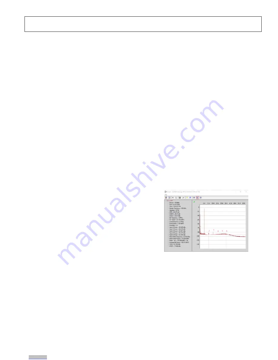
The I-channel and Q-channel are driven and measured
(refer to Figure 6). A sample FFT of the measurement is
shown in Figure 5.
The output loading is configured as follows:
10 Ω internal to μModule.
40 Ω on the EVAL-ADAQ8088EBZ.
33 Ω and 5 pF LPF on the EVAL-ADAQ8088EBZ
(still allows for optimization).
For details on the correct EVAL-ADAQ8088EBZ jumper
positions, modes of operation, and using the ADC data
capture software for testing, see the AD9681-125EBZ user
guide page at
https://wiki.analog.com/resources/eval/ad9681-
125ebz
.
Figure 5. Fast Fourier Transform (FFT) Result
25399-
008
Downloaded from
Downloaded from
Downloaded from
Downloaded from
Downloaded from
Downloaded from
Downloaded from


